
今回はNSX-TのDFWのExclusion Listについてまとめました。
概要
DFWのExclusion Listについて
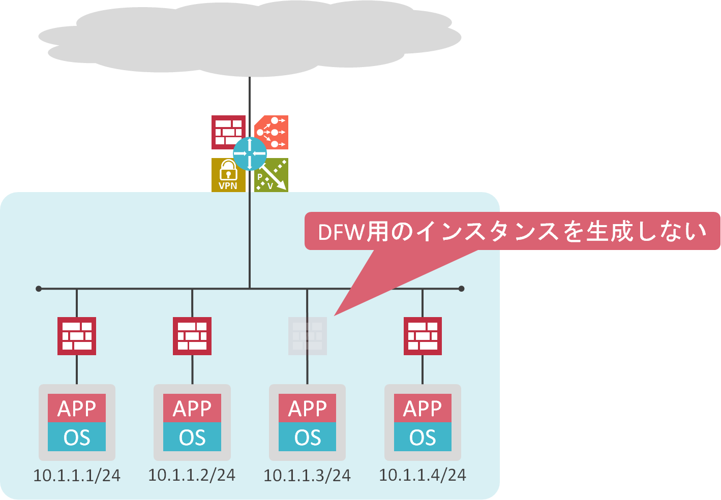
Exclusion Listを使用することで、特定の仮想マシンをDFWの保護対象から除外可能です。Exclusion Listに登録された仮想マシンのvNICのdvfilter slot 2にはDFW用のインスタンスは生成されません。
検証結果
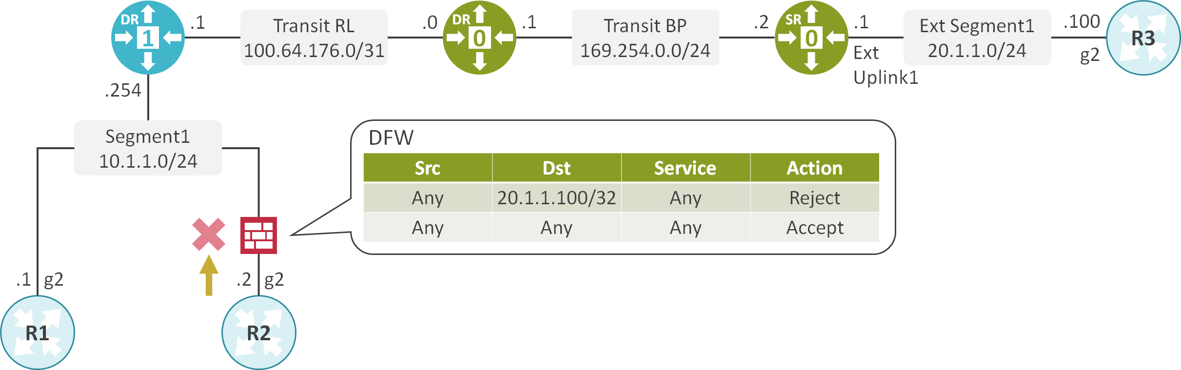
検証内容、構成
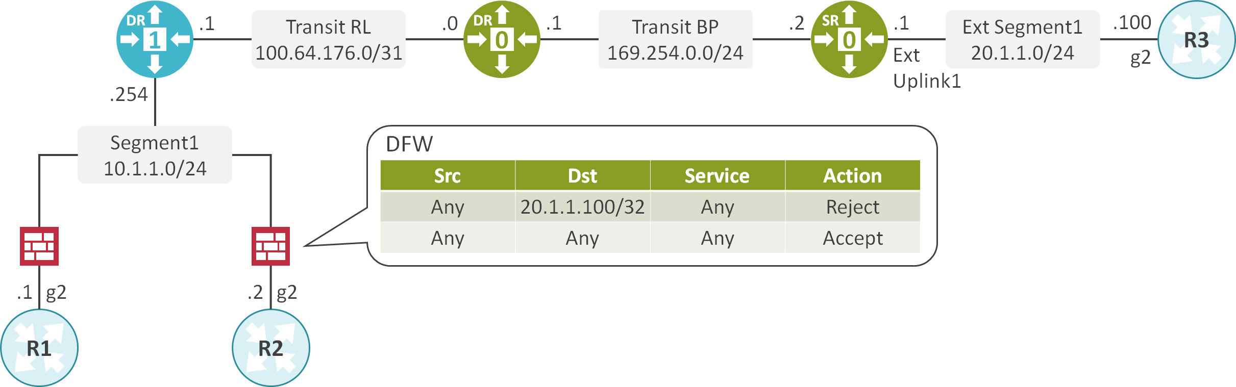
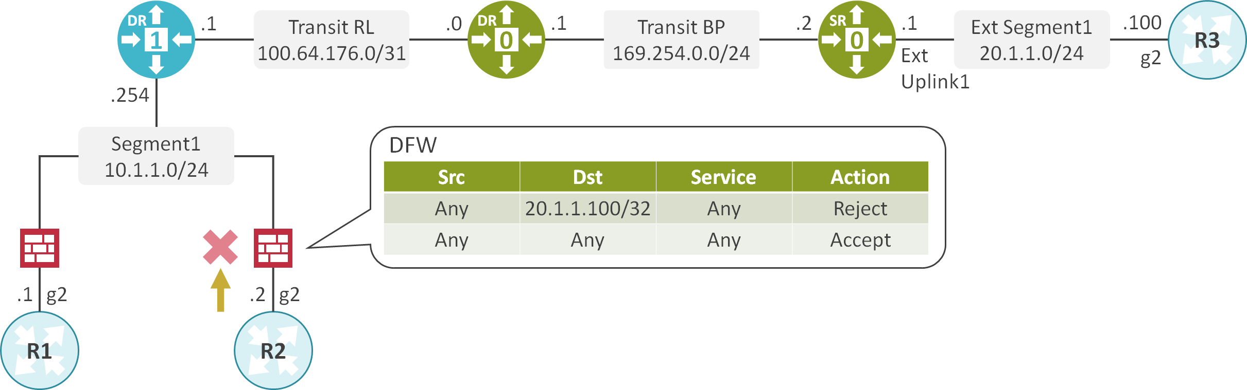
Tier-1 GWでSegment 1を収容します。
Tier-1 GWとTier-0 GWを接続します。
NSX EdgeにTier-0 GWのSRを配置し、物理ネットワークとNSX-Tの仮想ネットワークを接続します。
DFWに20.1.1.100宛のトラフィックを却下するルールを設定している状況で、Exclusion Listの設定を変更し、挙動を確認します。
ネットワーク機器のCLIの設定
interface GigabitEthernet2
 ip address 10.1.1.1 255.255.255.0
!
ip route 0.0.0.0 0.0.0.0 10.1.1.254
interface GigabitEthernet2
 ip address 10.1.1.2 255.255.255.0
!
ip route 0.0.0.0 0.0.0.0 10.1.1.254
interface GigabitEthernet2
 ip address 20.1.1.100 255.255.255.0
!
ip route 0.0.0.0 0.0.0.0 20.1.1.1
Exclusion List設定前
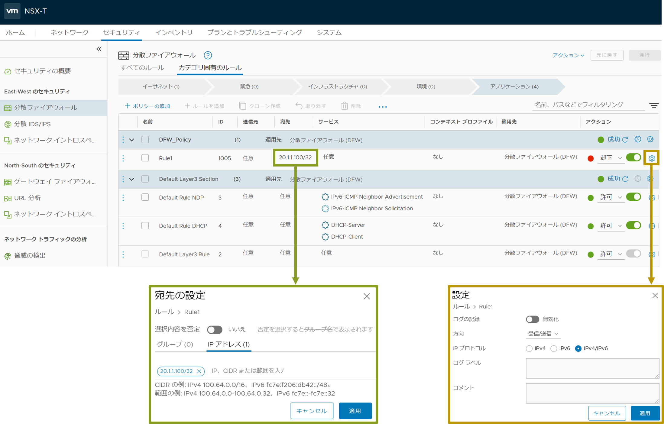
DFWの設定
DFWに20.1.1.100宛のトラフィックを却下するルールを追加します。
DFWの状態確認
R1とR2にDFWのルールが存在することが確認できます。
※R1のvNIC用のDFWのルール
[root@esxi1:~] vsipioctl getrules -f nic-2222203-eth1-vmware-sfw.2
ruleset mainrs {
  # generation number: 0
  # realization time : 2020-12-09T14:52:20
  # FILTER (APP Category) rules
  rule 1005 at 1 inout protocol any from any to ip 20.1.1.100 reject;
  rule 3 at 2 inout inet6 protocol ipv6-icmp icmptype 135 from any to any accept;
  rule 3 at 3 inout inet6 protocol ipv6-icmp icmptype 136 from any to any accept;
  rule 4 at 4 inout protocol udp from any to any port {67, 68} accept;
  rule 2 at 5 inout protocol any from any to any accept;
}

ruleset mainrs_L2 {
  # generation number: 0
  # realization time : 2020-12-09T14:52:20
  # FILTER rules
  rule 1 at 1 inout ethertype any stateless from any to any accept;
}


※R2のvNIC用のDFWのルール
[root@esxi1:~] vsipioctl getrules -f nic-4566697-eth1-vmware-sfw.2
ruleset mainrs {
  # generation number: 0
  # realization time : 2020-12-09T14:48:04
  # FILTER (APP Category) rules
  rule 1005 at 1 inout protocol any from any to ip 20.1.1.100 reject;
  rule 3 at 2 inout inet6 protocol ipv6-icmp icmptype 135 from any to any accept;
  rule 3 at 3 inout inet6 protocol ipv6-icmp icmptype 136 from any to any accept;
  rule 4 at 4 inout protocol udp from any to any port {67, 68} accept;
  rule 2 at 5 inout protocol any from any to any accept;
}

ruleset mainrs_L2 {
  # generation number: 0
  # realization time : 2020-12-09T14:48:04
  # FILTER rules
  rule 1 at 1 inout ethertype any stateless from any to any accept;
}
疎通確認
R1の10.1.1.1からR3の20.1.1.100にPingを実施します。
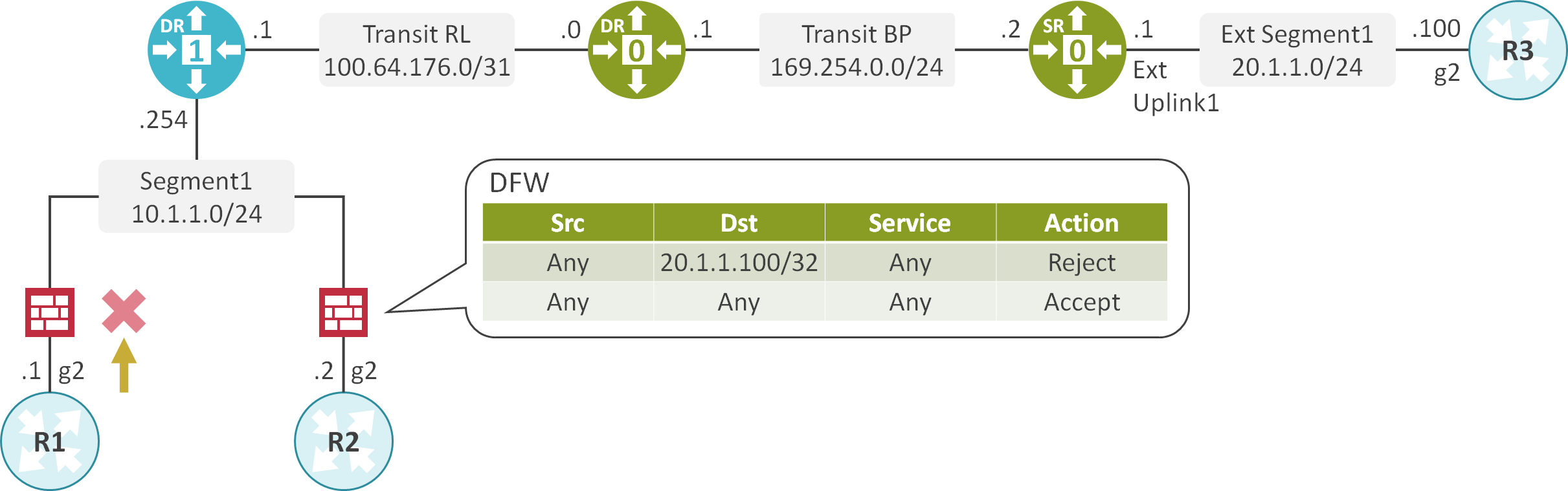
R1の10.1.1.1からR3の20.1.1.100へのPingが失敗することが確認できます。
R1#ping 20.1.1.100 source 10.1.1.1
Type escape sequence to abort.
Sending 5, 100-byte ICMP Echos to 20.1.1.100, timeout is 2 seconds:
Packet sent with a source address of 10.1.1.1
UUUUU
Success rate is 0 percent (0/5)
R2の10.1.1.2からR3の20.1.1.100にPingを実施します。
R2の10.1.1.2からR3の20.1.1.100へのPingが失敗することが確認できます。
R2#ping 20.1.1.100 source 10.1.1.2
Type escape sequence to abort.
Sending 5, 100-byte ICMP Echos to 20.1.1.100, timeout is 2 seconds:
Packet sent with a source address of 10.1.1.2
UUUUU
Success rate is 0 percent (0/5)
Exclusion List設定後
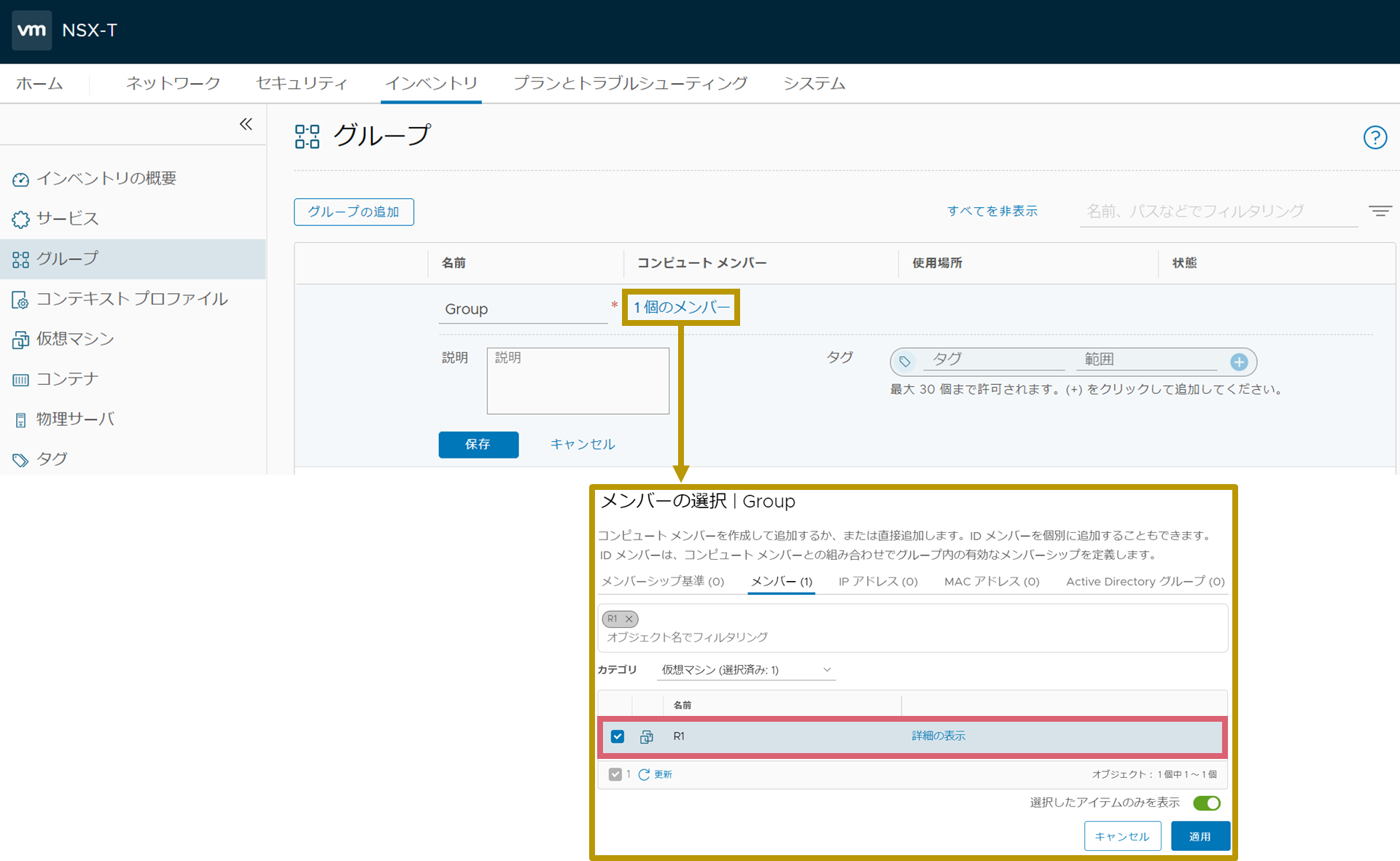
Groupの設定
Groupを定義し、R1を指定します。
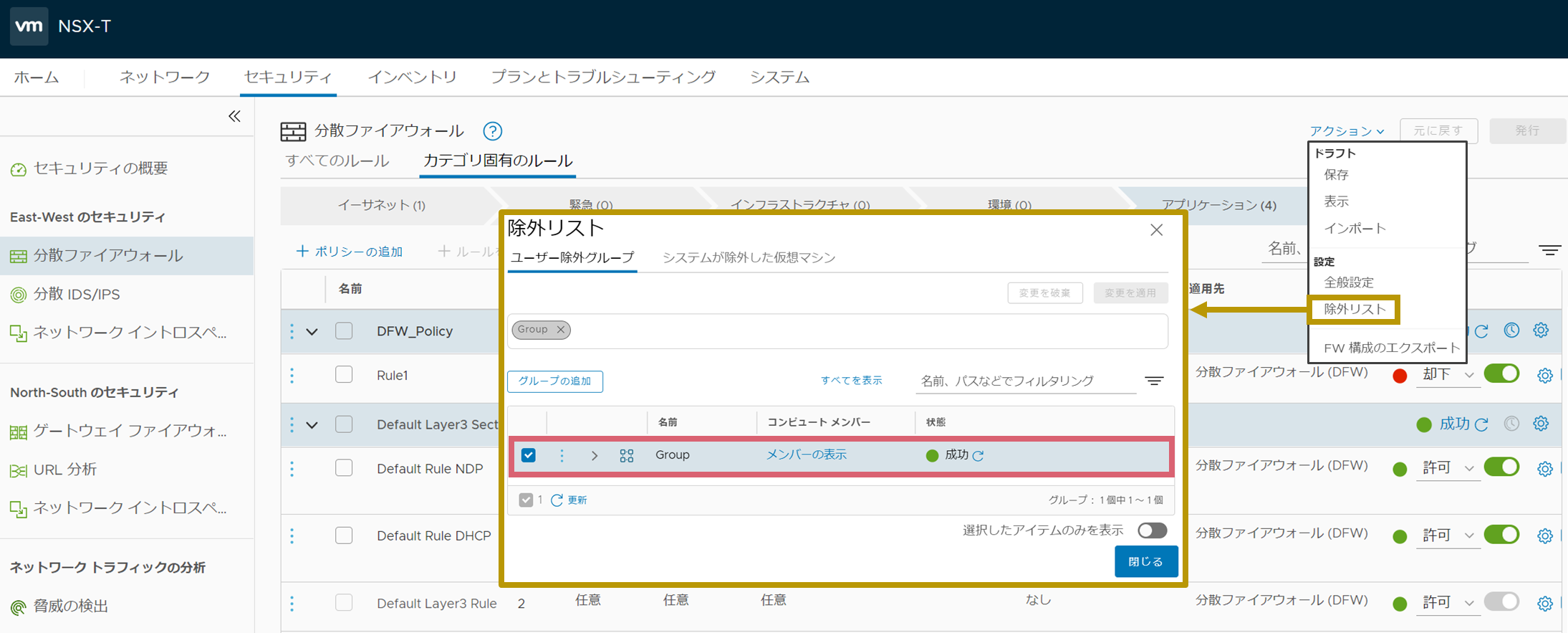
DFWの設定
DFWのExclusion Listに先程作成したGroupを指定します。
DFWの状態確認
R1のDFWが消失したことが確認できます。
※R1のvNIC用のDFWのルール
[root@esxi1:~] vsipioctl getrules -f nic-2222203-eth1-vmware-sfw.2
ERROR: failed to get total rulesets: switch port not found


※R2のvNIC用のDFWのルール
[root@esxi1:~] vsipioctl getrules -f nic-4566697-eth1-vmware-sfw.2
ruleset mainrs {
  # generation number: 0
  # realization time : 2020-12-09T14:48:04
  # FILTER (APP Category) rules
  rule 1005 at 1 inout protocol any from any to ip 20.1.1.100 reject;
  rule 3 at 2 inout inet6 protocol ipv6-icmp icmptype 135 from any to any accept;
  rule 3 at 3 inout inet6 protocol ipv6-icmp icmptype 136 from any to any accept;
  rule 4 at 4 inout protocol udp from any to any port {67, 68} accept;
  rule 2 at 5 inout protocol any from any to any accept;
}

ruleset mainrs_L2 {
  # generation number: 0
  # realization time : 2020-12-09T14:48:04
  # FILTER rules
  rule 1 at 1 inout ethertype any stateless from any to any accept;
}
疎通確認
R1の10.1.1.1からR3の20.1.1.100にPingを実施します。
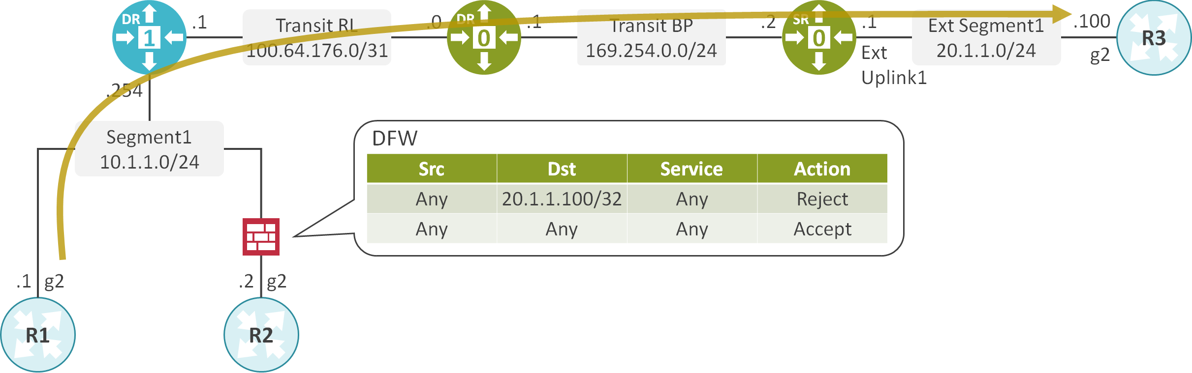
R1の10.1.1.1からR3の20.1.1.100へのPingが成功することが確認できます。
R1#ping 20.1.1.100 source 10.1.1.1
Type escape sequence to abort.
Sending 5, 100-byte ICMP Echos to 20.1.1.100, timeout is 2 seconds:
Packet sent with a source address of 10.1.1.1
!!!!!
Success rate is 100 percent (5/5), round-trip min/avg/max = 1/1/1 ms
R2の10.1.1.2からR3の20.1.1.100にPingを実施します。
R2の10.1.1.2からR3の20.1.1.100へのPingが失敗することが確認できます。
R2#ping 20.1.1.100 source 10.1.1.2
Type escape sequence to abort.
Sending 5, 100-byte ICMP Echos to 20.1.1.100, timeout is 2 seconds:
Packet sent with a source address of 10.1.1.2
UUUUU
Success rate is 0 percent (0/5)

コメント