
今回はNSX-Tのマイクロセグメンテーションの概要とDistributed FWの簡単な検証証跡についてまとめました。
概要
マイクロセグメンテーションについて
従来のネットワークでは、ネットワークセグメントの境界にファイアウォールを設置するため、同じネットワークセグメント内に存在する仮想マシン間の通信を制御することは困難でした。 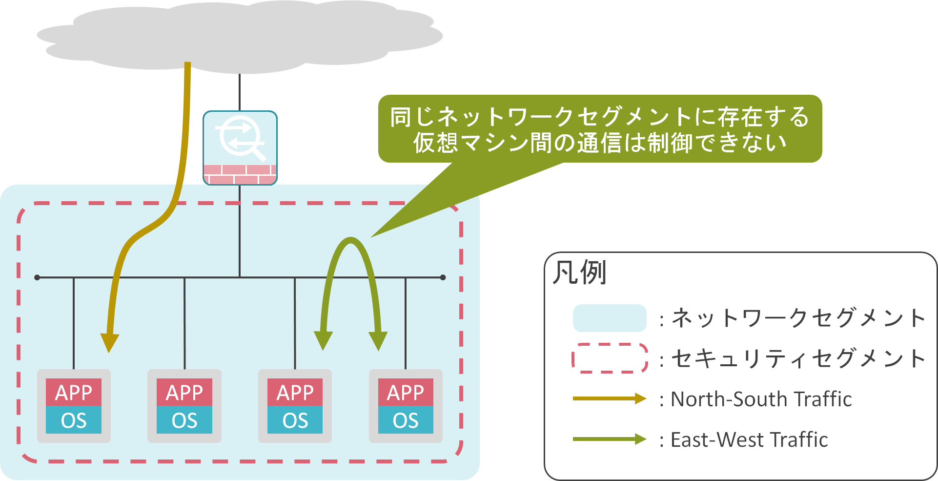
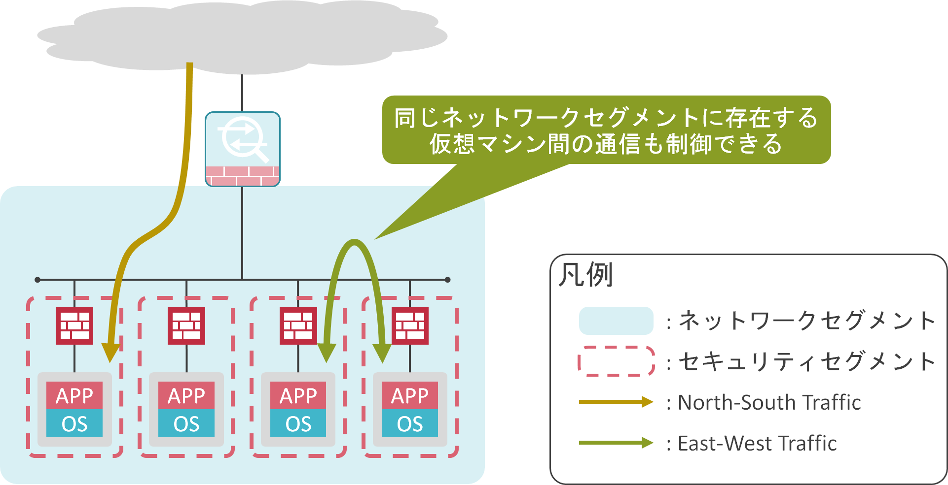
NSX-Tでは、仮想マシンのvNIC毎にファイアウォールを設置することで、同じネットワークセグメント内に存在する仮想マシン間の通信制御を実現可能で、このファイアウォールのことをDFW(Distributed Firewall)と呼びます。
NSX-Tでは、今までネットワークセグメントと同じ大きさだったセキュリティセグメントを仮想マシン単位まで細かく分割し、細かくなったセキュリティセグメント毎にセキュリティ機能を適用します。このような考え方をマイクロセグメンテーションと呼びます。
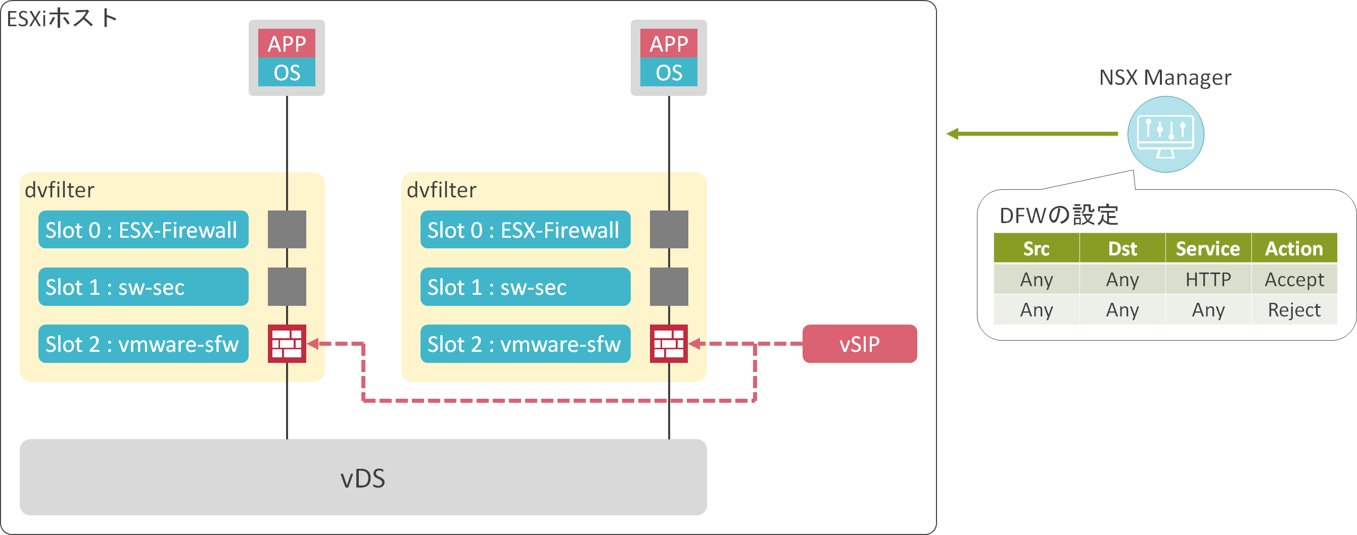
DFWは仮想マシンのvNICとvDSとの間に存在するdvfilterのslot 2で動作しています。NSX Managerで設定したDFWの設定内容がESXiホストに転送されます。その後、ESXiホスト内で動作しているvSIP(VMware Internetworking Service Insertion Platform)と呼ばれるカーネルモジュールが各vNICのdvfilterのslot 2に対して、DFWの設定を適用します。
検証結果
検証内容、構成
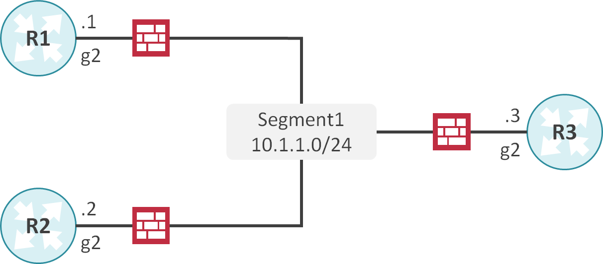
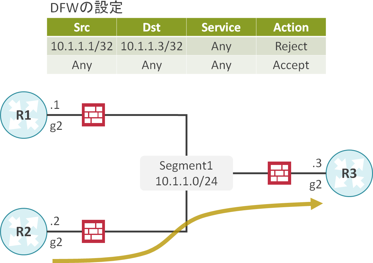
Segment 1にR1~R3を収容します。
DFWで送信元アドレスが10.1.1.1、送信先アドレスが10.1.1.3のトラフィックをブロックします。
ネットワーク機器のCLIの設定
interface GigabitEthernet2
 ip address 10.1.1.1 255.255.255.0
interface GigabitEthernet2
 ip address 10.1.1.2 255.255.255.0
interface GigabitEthernet2
 ip address 10.1.1.3 255.255.255.0
DFW設定前
DFWの状態確認
最初にsummarize-dvfilterコマンドを使用して、各vNICのdvfilterのslot 2のインスタンスの名前を取得します。
[root@esxi1:~] summarize-dvfilter
Fastpaths:
agent: vmware-si, refCount: 1, rev: 0x1010000, apiRev: 0x1010000, module: nsxt-vsip-17107169
agent: vmware-sfw, refCount: 28, rev: 0x1010000, apiRev: 0x1010000, module: nsxt-vsip-17107169
agent: nsx_bridgelearningfilter, refCount: 1, rev: 0x1010000, apiRev: 0x1010000, module: nsxt-vdrb-17107169
agent: dvfilter-generic-vmware, refCount: 1, rev: 0x1010000, apiRev: 0x1010000, module: dvfilter-generic-fastpath
agent: ESXi-Firewall, refCount: 4, rev: 0x1010000, apiRev: 0x1010000, module: esxfw
agent: dvfilter-faulter, refCount: 1, rev: 0x1010000, apiRev: 0x1010000, module: dvfilter

ServiceVMs:
serviceVM: 3, agent vmware-sfw, refCount: 2, rev: 0x4, apiRev: 0x4, capabilities: csum,tso
serviceVM: 4, agent vmware-sfw, refCount: 1, rev: 0x4, apiRev: 0x4, capabilities: csum,tso

Filters:
world 2222203 vmm0:R1 vcUuid:'50 39 56 48 7d 8f 78 0b-e7 a0 09 89 e1 fc 1d 13'
 port 67109092 R1.eth1
  vNic slot 2
   name: nic-2222203-eth1-vmware-sfw.2
   agentName: vmware-sfw
   state: IOChain Attached
   vmState: Attached
   failurePolicy: failClosed
   serviceVMID: 3
   filter source: Dynamic Filter Creation
   moduleName: nsxt-vsip-17107169
world 4566697 vmm0:R2 vcUuid:'50 39 54 dd c1 24 9f dc-7c 38 ce d4 d7 4d 5a 0a'
 port 67109105 R2.eth1
  vNic slot 2
   name: nic-4566697-eth1-vmware-sfw.2
   agentName: vmware-sfw
   state: IOChain Attached
   vmState: Attached
   failurePolicy: failClosed
   serviceVMID: 4
   filter source: Dynamic Filter Creation
   moduleName: nsxt-vsip-17107169
次にsipioctl getrules -f <名前>コマンドを使用して、dvfilterのslot 2に適用されているDFWの設定を確認します。R1とR2共にDFWのルールが存在することが確認できます。(もちろんR3のdvfilter slot 2でもDFWは動作しています。)
[root@esxi1:~] vsipioctl getrules -f nic-2222203-eth1-vmware-sfw.2
ruleset mainrs {
  # generation number: 0
  # realization time : 2020-12-09T13:42:55
  # FILTER (APP Category) rules
  rule 3 at 1 inout inet6 protocol ipv6-icmp icmptype 135 from any to any accept;
  rule 3 at 2 inout inet6 protocol ipv6-icmp icmptype 136 from any to any accept;
  rule 4 at 3 inout protocol udp from any to any port {67, 68} accept;
  rule 2 at 4 inout protocol any from any to any accept;
}

ruleset mainrs_L2 {
  # generation number: 0
  # realization time : 2020-12-09T13:42:55
  # FILTER rules
  rule 1 at 1 inout ethertype any stateless from any to any accept;
}


[root@esxi1:~] vsipioctl getrules -f nic-4566697-eth1-vmware-sfw.2
ruleset mainrs {
  # generation number: 0
  # realization time : 2020-12-09T13:52:25
  # FILTER (APP Category) rules
  rule 3 at 1 inout inet6 protocol ipv6-icmp icmptype 135 from any to any accept;
  rule 3 at 2 inout inet6 protocol ipv6-icmp icmptype 136 from any to any accept;
  rule 4 at 3 inout protocol udp from any to any port {67, 68} accept;
  rule 2 at 4 inout protocol any from any to any accept;
}

ruleset mainrs_L2 {
  # generation number: 0
  # realization time : 2020-12-09T13:52:25
  # FILTER rules
  rule 1 at 1 inout ethertype any stateless from any to any accept;
}
疎通確認
R1の10.1.1.1からR3の10.1.1.3にPingを実施します。
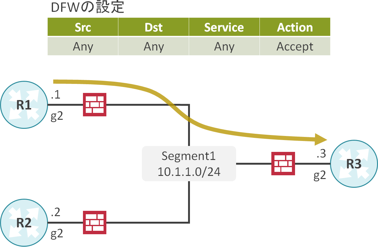
R1の10.1.1.1からR3の10.1.1.3へのPingが成功することが確認できます。
R1#ping 10.1.1.3 source 10.1.1.1
Type escape sequence to abort.
Sending 5, 100-byte ICMP Echos to 10.1.1.3, timeout is 2 seconds:
Packet sent with a source address of 10.1.1.1
!!!!!
Success rate is 100 percent (5/5), round-trip min/avg/max = 1/1/1 ms
R2の10.1.1.2からR3の10.1.1.3にPingを実施します。
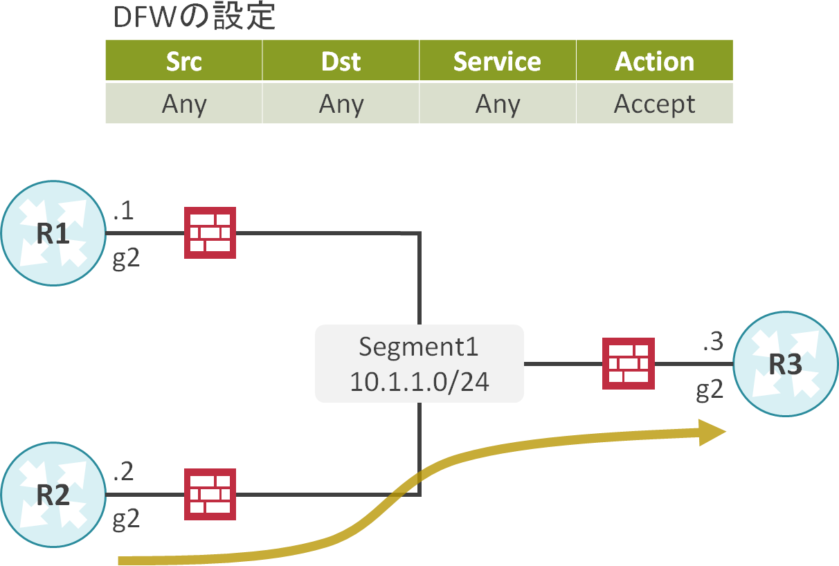
R2の10.1.1.2からR3の10.1.1.3へのPingが成功することが確認できます。
R2#ping 10.1.1.3 source 10.1.1.2
Type escape sequence to abort.
Sending 5, 100-byte ICMP Echos to 10.1.1.3, timeout is 2 seconds:
Packet sent with a source address of 10.1.1.2
!!!!!
Success rate is 100 percent (5/5), round-trip min/avg/max = 1/1/1 ms
DFW設定後
DFWの設定
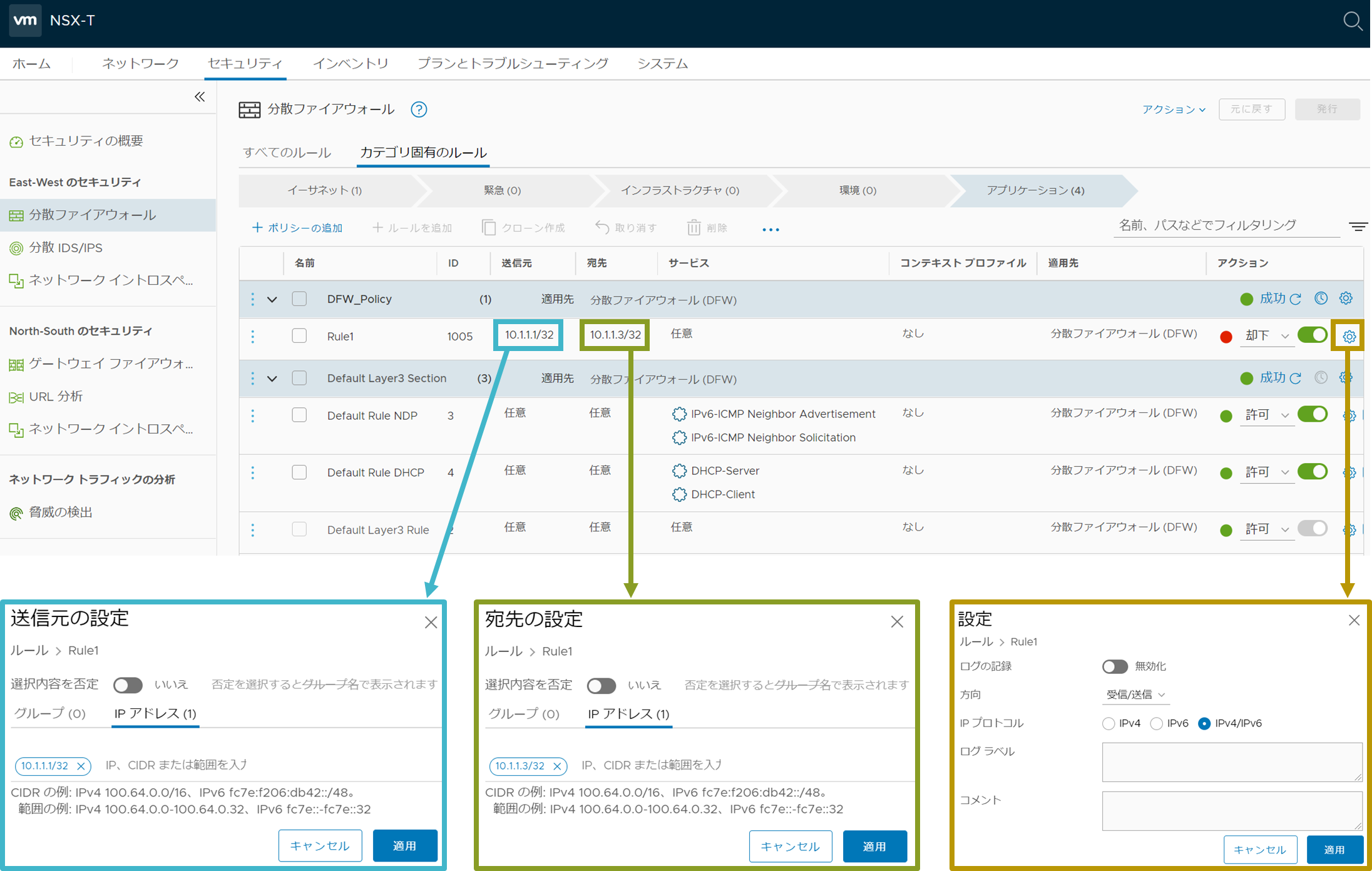
DFWに送信元アドレスが10.1.1.1/32、送信先アドレスが10.1.1.3/32のトラフィックを却下するルールを追加します。
DFWの状態確認
R1とR2にDFWのルールが追加されたことが確認できます。
[root@esxi1:~] vsipioctl getrules -f nic-2222203-eth1-vmware-sfw.2
ruleset mainrs {
  # generation number: 0
  # realization time : 2020-12-09T13:42:55
  # FILTER (APP Category) rules
  rule 1005 at 1 inout protocol any from ip 10.1.1.1 to ip 10.1.1.3 reject;
  rule 3 at 1 inout inet6 protocol ipv6-icmp icmptype 135 from any to any accept;
  rule 3 at 2 inout inet6 protocol ipv6-icmp icmptype 136 from any to any accept;
  rule 4 at 3 inout protocol udp from any to any port {67, 68} accept;
  rule 2 at 4 inout protocol any from any to any accept;
}

ruleset mainrs_L2 {
  # generation number: 0
  # realization time : 2020-12-09T13:42:55
  # FILTER rules
  rule 1 at 1 inout ethertype any stateless from any to any accept;
}


[root@esxi1:~] vsipioctl getrules -f nic-4566697-eth1-vmware-sfw.2
ruleset mainrs {
  # generation number: 0
  # realization time : 2020-12-09T13:52:25
  # FILTER (APP Category) rules
  rule 1005 at 1 inout protocol any from ip 10.1.1.1 to ip 10.1.1.3 reject;
  rule 3 at 1 inout inet6 protocol ipv6-icmp icmptype 135 from any to any accept;
  rule 3 at 2 inout inet6 protocol ipv6-icmp icmptype 136 from any to any accept;
  rule 4 at 3 inout protocol udp from any to any port {67, 68} accept;
  rule 2 at 4 inout protocol any from any to any accept;
}

ruleset mainrs_L2 {
  # generation number: 0
  # realization time : 2020-12-09T13:52:25
  # FILTER rules
  rule 1 at 1 inout ethertype any stateless from any to any accept;
}
疎通確認
R1の10.1.1.1からR3の10.1.1.3にPingを実施します。
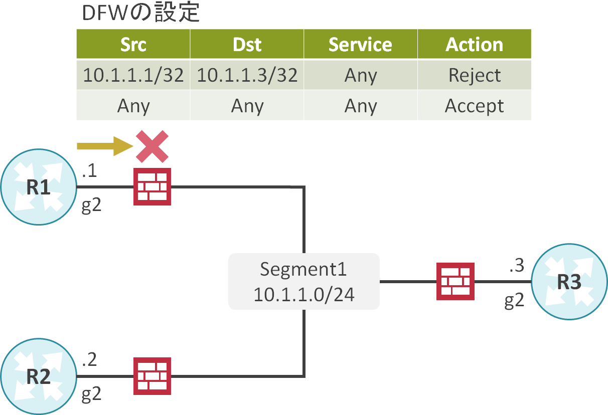
R1の10.1.1.1からR3の10.1.1.3へのPingが失敗することが確認できます。
R1#ping 10.1.1.3 source 10.1.1.1
Type escape sequence to abort.
Sending 5, 100-byte ICMP Echos to 10.1.1.3, timeout is 2 seconds:
Packet sent with a source address of 10.1.1.1
UUUUU
Success rate is 0 percent (0/5)
R2の10.1.1.2からR3の10.1.1.3にPingを実施します。
R2の10.1.1.2からR3の10.1.1.3へのPingが成功することが確認できます。
R2#ping 10.1.1.3 source 10.1.1.2
Type escape sequence to abort.
Sending 5, 100-byte ICMP Echos to 10.1.1.3, timeout is 2 seconds:
Packet sent with a source address of 10.1.1.2
!!!!!
Success rate is 100 percent (5/5), round-trip min/avg/max = 1/1/1 ms

コメント