今回はOSPFのNBMAについて解説します。
座学
NBMAについて
例えば、下図の様に、ISP(Internet Service Provider)が提供しているWAN接続サービスを使用して、離れた拠点間を接続し、かつ、離れた拠点間でOSPFを使用してルート情報を交換したいケースが存在します。しかし、一部のWAN接続サービスではブロードキャストやマルチキャストの転送をサポートしていない場合があります。

OSPFでは、上記の様なブロードキャストとマルチキャストをサポートしていないネットワークのことをNBMA(Non-Broadcast Multi Access)ネットワークと呼びます。
NBMAにおいては、各ルータでネイバーのアドレスを明示的に指定することで、マルチキャストを使用せずに、ネイバーを確立することが可能です。
NBMAにおいて、OSPFは以下の2種類のNetwork Typeを使用可能です。
- Non-Broadcast
- Point-to-Multipoint Non-Broadcast
Non-Broadcastネットワークでは、Broadcastネットワークと同様にLSA Type 1とLSA Type 2を生成します。

実機での動作確認
検証内容
R1のg2、R2のg2とg3でOSPF Area 0を有効にします。
10.1.1.0/24のNetwork TypeにはNon Broadcastを使用します。

初期設定
interface GigabitEthernet2
 ip address 10.1.1.1 255.255.255.0
 ip ospf network non-broadcast
!
router ospf 1
 router-id 1.1.1.1
 network 10.1.1.0 0.0.0.255 area 0
 neighbor 10.1.1.2
interface GigabitEthernet2
 ip address 10.1.1.2 255.255.255.0
 ip ospf network non-broadcast
!
interface GigabitEthernet3
 ip address 10.2.2.2 255.255.255.0
!
router ospf 1
 router-id 2.2.2.2
 network 10.1.1.0 0.0.0.255 area 0
 network 10.2.2.0 0.0.0.255 area 0
 neighbor 10.1.1.1
コマンドの確認
ip ospf network non-broadcastコマンドを使用することで、インタフェースのNetwork TypeをNon-Broadcastに変更可能です。
また、ネイバーを確立する対向のルータのIPアドレスはneighbor <address>コマンドで指定します。
interface GigabitEthernet2
 ip ospf network non-broadcast
!
router ospf 1
 neighbor 10.1.1.2
OSPFが動作しているインタフェースの状態確認
R1のg2のNetwork TypeがNon-Broadcastであることが確認できます。
R1#show ip ospf interface
GigabitEthernet2 is up, line protocol is up
  Internet Address 10.1.1.1/24, Interface ID 6, Area 0
  Attached via Network Statement
  Process ID 1, Router ID 1.1.1.1, Network Type NON_BROADCAST, Cost: 1
  Topology-MTID    Cost    Disabled    Shutdown      Topology Name
        0           1         no          no            Base
  Transmit Delay is 1 sec, State BDR, Priority 1
  Designated Router (ID) 2.2.2.2, Interface address 10.1.1.2
  Backup Designated router (ID) 1.1.1.1, Interface address 10.1.1.1
  Flush timer for old DR LSA due in 00:02:28
  Timer intervals configured, Hello 30, Dead 120, Wait 120, Retransmit 5
    oob-resync timeout 120
    Hello due in 00:00:18
  Supports Link-local Signaling (LLS)
  Cisco NSF helper support enabled
  IETF NSF helper support enabled
  Index 1/1/1, flood queue length 0
  Next 0x0(0)/0x0(0)/0x0(0)
  Last flood scan length is 1, maximum is 1
  Last flood scan time is 0 msec, maximum is 0 msec
  Neighbor Count is 1, Adjacent neighbor count is 1
    Adjacent with neighbor 2.2.2.2  (Designated Router)
  Suppress hello for 0 neighbor(s)
OSPFネイバーの状態確認
Non-BroadcastやPoint-to-Multipoint Non-BroadcastネットワークではネイバーからHelloパケットを受信する前の状態をAttemptと呼びます。
R1#show ip ospf neighbor detail
 Neighbor N/A, interface address 10.1.1.2
    In the area 0 via interface GigabitEthernet2
    Neighbor priority is 0 (configured 0), State is ATTEMPT, 1 state changes
    DR is 0.0.0.0 BDR is 0.0.0.0
    Poll interval 120
    Options is 0x0 in Hello
    Dead timer due in 00:01:09
    Index 0/0/0, retransmission queue length 0, number of retransmission 0
    First 0x0(0)/0x0(0)/0x0(0) Next 0x0(0)/0x0(0)/0x0(0)
    Last retransmission scan length is 0, maximum is 0
    Last retransmission scan time is 0 msec, maximum is 0 msec
ネイバーからHelloパケットを受信し、LSDBの同期が完了すると、Full状態に遷移します。
R1#show ip ospf neighbor detail
 Neighbor 2.2.2.2, interface address 10.1.1.2, interface-id 6
    In the area 0 via interface GigabitEthernet2
    Neighbor priority is 1 (configured 0), State is FULL, 8 state changes
    DR is 10.1.1.2 BDR is 10.1.1.1
    Poll interval 120
    Options is 0x12 in Hello (E-bit, L-bit)
    Options is 0x52 in DBD (E-bit, L-bit, O-bit)
    LLS Options is 0x1 (LR)
    Dead timer due in 00:01:54
    Neighbor is up for 00:00:36
    Index 1/1/1, retransmission queue length 0, number of retransmission 0
    First 0x0(0)/0x0(0)/0x0(0) Next 0x0(0)/0x0(0)/0x0(0)
    Last retransmission scan length is 0, maximum is 0
    Last retransmission scan time is 0 msec, maximum is 0 msec
Helloパケットの確認
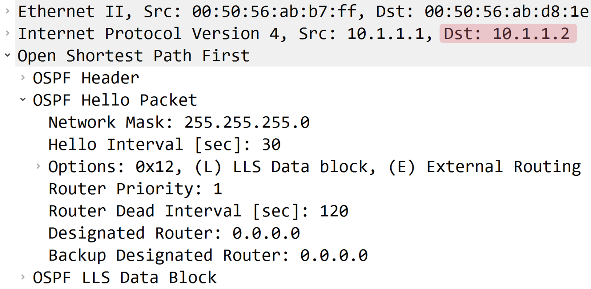
R1はR2宛にユニキャストでHelloパケットを送信していることが確認できます。
R1#debug ip ospf hello
*Jun  4 00:50:43.065: OSPF-1 HELLO Gi2: Send hello to 10.1.1.2 area 0 from 10.1.1.1

LSDBの状態確認

LSA Type 1とLSA Type 2が生成されていることが確認できます。
R1#show ip ospf database

            OSPF Router with ID (1.1.1.1) (Process ID 1)

                Router Link States (Area 0)

Link ID         ADV Router      Age         Seq#       Checksum Link count
1.1.1.1         1.1.1.1         258         0x80000003 0x009C71 1
2.2.2.2         2.2.2.2         245         0x8000000B 0x008954 2

                Net Link States (Area 0)

Link ID         ADV Router      Age         Seq#       Checksum
10.1.1.2        2.2.2.2         259         0x80000001 0x002CEB
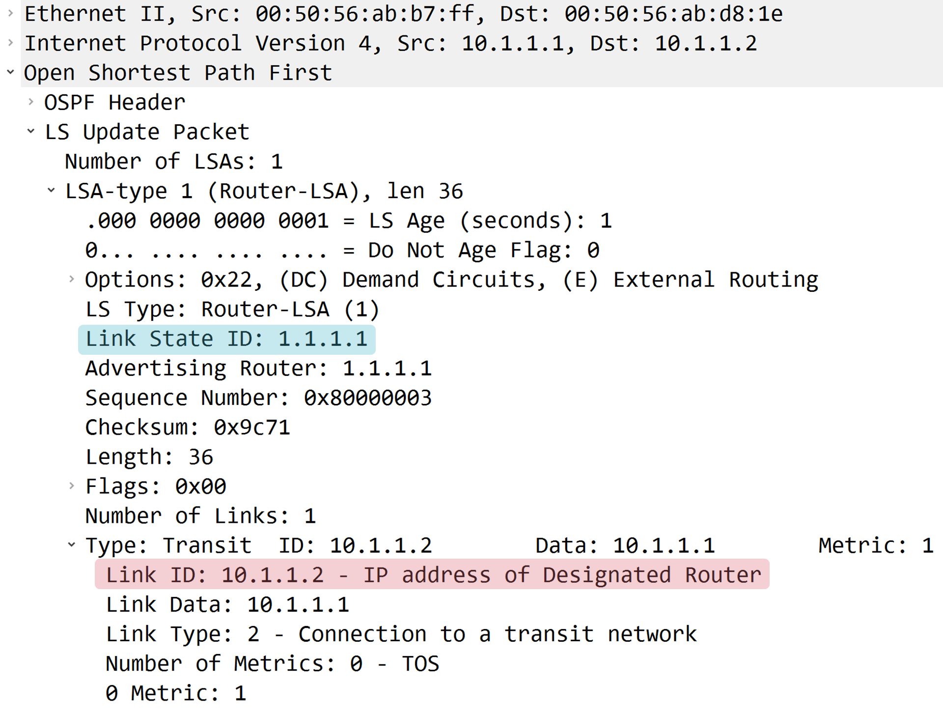
R1が生成したLSA Type 1には、DRであるR2のIPアドレスの情報が格納されていることが確認できます。
R1#show ip ospf database router adv-router 1.1.1.1

            OSPF Router with ID (1.1.1.1) (Process ID 1)

                Router Link States (Area 0)

  LS age: 265
  Options: (No TOS-capability, DC)
  LS Type: Router Links
  Link State ID: 1.1.1.1
  Advertising Router: 1.1.1.1
  LS Seq Number: 80000003
  Checksum: 0x9C71
  Length: 36
  Number of Links: 1

    Link connected to: a Transit Network
     (Link ID) Designated Router address: 10.1.1.2
     (Link Data) Router Interface address: 10.1.1.1
      Number of MTID metrics: 0
       TOS 0 Metrics: 1

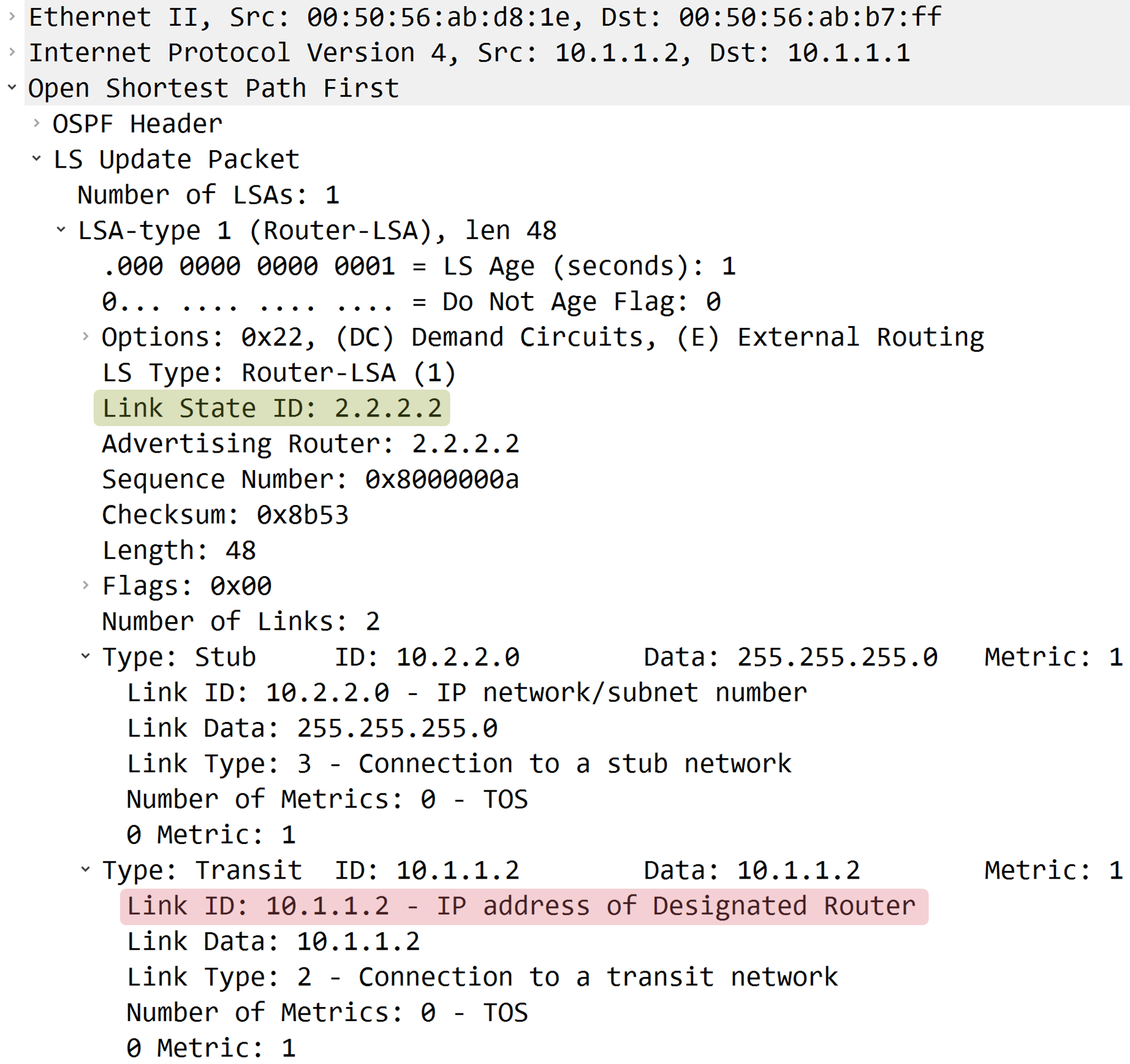
R2が生成したLSA Type 1には、DRであるR2のIPアドレスの情報が格納されていることが確認できます。
R2#show ip ospf database router adv-router 2.2.2.2

            OSPF Router with ID (1.1.1.1) (Process ID 1)

                Router Link States (Area 0)

  LS age: 254
  Options: (No TOS-capability, DC)
  LS Type: Router Links
  Link State ID: 2.2.2.2
  Advertising Router: 2.2.2.2
  LS Seq Number: 8000000A
  Checksum: 0x8B53
  Length: 48
  Number of Links: 2

    Link connected to: a Stub Network
     (Link ID) Network/subnet number: 10.2.2.0
     (Link Data) Network Mask: 255.255.255.0
      Number of MTID metrics: 0
       TOS 0 Metrics: 1

    Link connected to: a Transit Network
     (Link ID) Designated Router address: 10.1.1.2
     (Link Data) Router Interface address: 10.1.1.2
      Number of MTID metrics: 0
       TOS 0 Metrics: 1

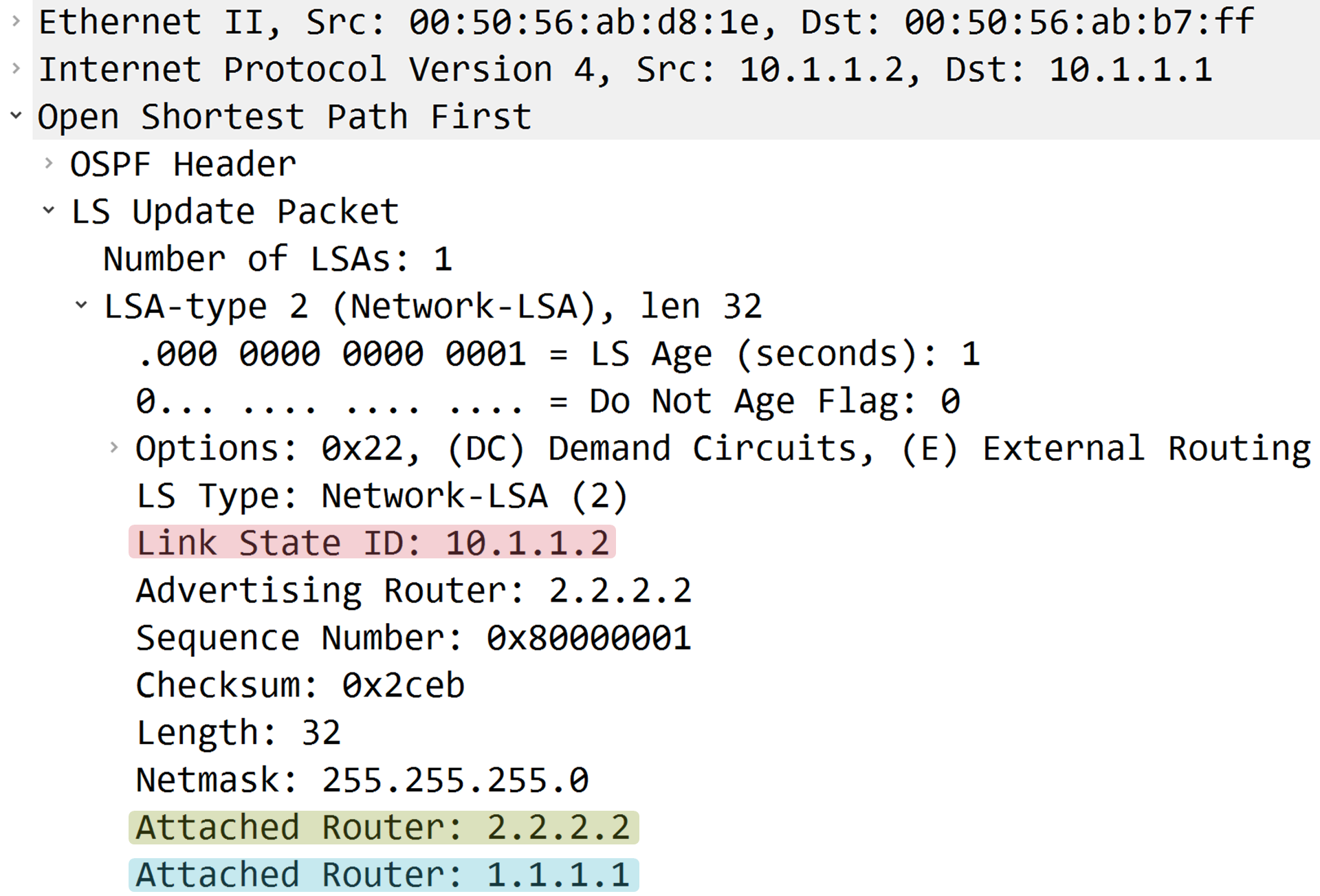
R2が生成したLSA Type 2には、R1とR2のRouter IDが格納されていることが確認できます。
R2#show ip ospf database network 10.1.1.2 adv-router 2.2.2.2

            OSPF Router with ID (1.1.1.1) (Process ID 1)

                Net Link States (Area 0)

  LS age: 279
  Options: (No TOS-capability, DC)
  LS Type: Network Links
  Link State ID: 10.1.1.2 (address of Designated Router)
  Advertising Router: 2.2.2.2
  LS Seq Number: 80000001
  Checksum: 0x2CEB
  Length: 32
  Network Mask: /24
        Attached Router: 2.2.2.2
        Attached Router: 1.1.1.1

SPFの計算結果の確認
R1はNon-Broadcastネットワーク経由で学習した10.2.2.0/24のネクストホップを正しく求められていることが確認できます。
R1#show ip ospf rib

            OSPF Router with ID (1.1.1.1) (Process ID 1)

                Base Topology (MTID 0)

OSPF local RIB
Codes: * - Best, > - Installed in global RIB

*   10.1.1.0/24, Intra, cost 1, area 0, Connected
      via 10.1.1.1, GigabitEthernet2
*>  10.2.2.0/24, Intra, cost 2, area 0
      via 10.1.1.2, GigabitEthernet2
ルーティングテーブルの確認
R1のルーティングテーブルに10.2.2.0/24が存在することが確認できます。
R1#show ip route ospf
      10.0.0.0/8 is variably subnetted, 3 subnets, 2 masks
O        10.2.2.0/24 [110/2] via 10.1.1.2, 00:00:59, GigabitEthernet2
疎通確認

R1の10.1.1.1からR2の10.2.2.2へのPingが成功したため、R1はNon-Broadcastネットワーク経由で学習したネットワークとの疎通可能なことが確認できます。
R1#ping 10.2.2.2 source 10.1.1.1
Type escape sequence to abort.
Sending 5, 100-byte ICMP Echos to 10.2.2.2, timeout is 2 seconds:
Packet sent with a source address of 10.1.1.1
!!!!!
Success rate is 100 percent (5/5), round-trip min/avg/max = 1/1/1 ms


コメント