今回はDisjoint Pathを使用して、既に計算済みのLSPが使用中のリンクと同じSRLGに所属しているリンクを経由しないように、新規のLSPを計算する方法を説明しました。
概要
SRLGについて
以下の図で、R3で筐体障害が発生した場合、R2のg3とg4のリンクが同時にダウンします。
このように、何か障害が発生した際に、同時に影響を受けるリンクのグループをSRLG(Shared Risk Link Group)と呼びます。

OSPFやIS-ISでは、リンクが所属するSRLGの情報を広報可能です。
以下はOSPFのSRLG用のSub-TLVのフォーマットになります。

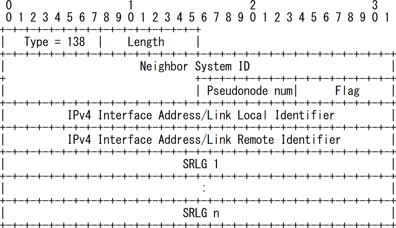
以下はIS-ISのSRLG用のSub-TLVのフォーマットになります。
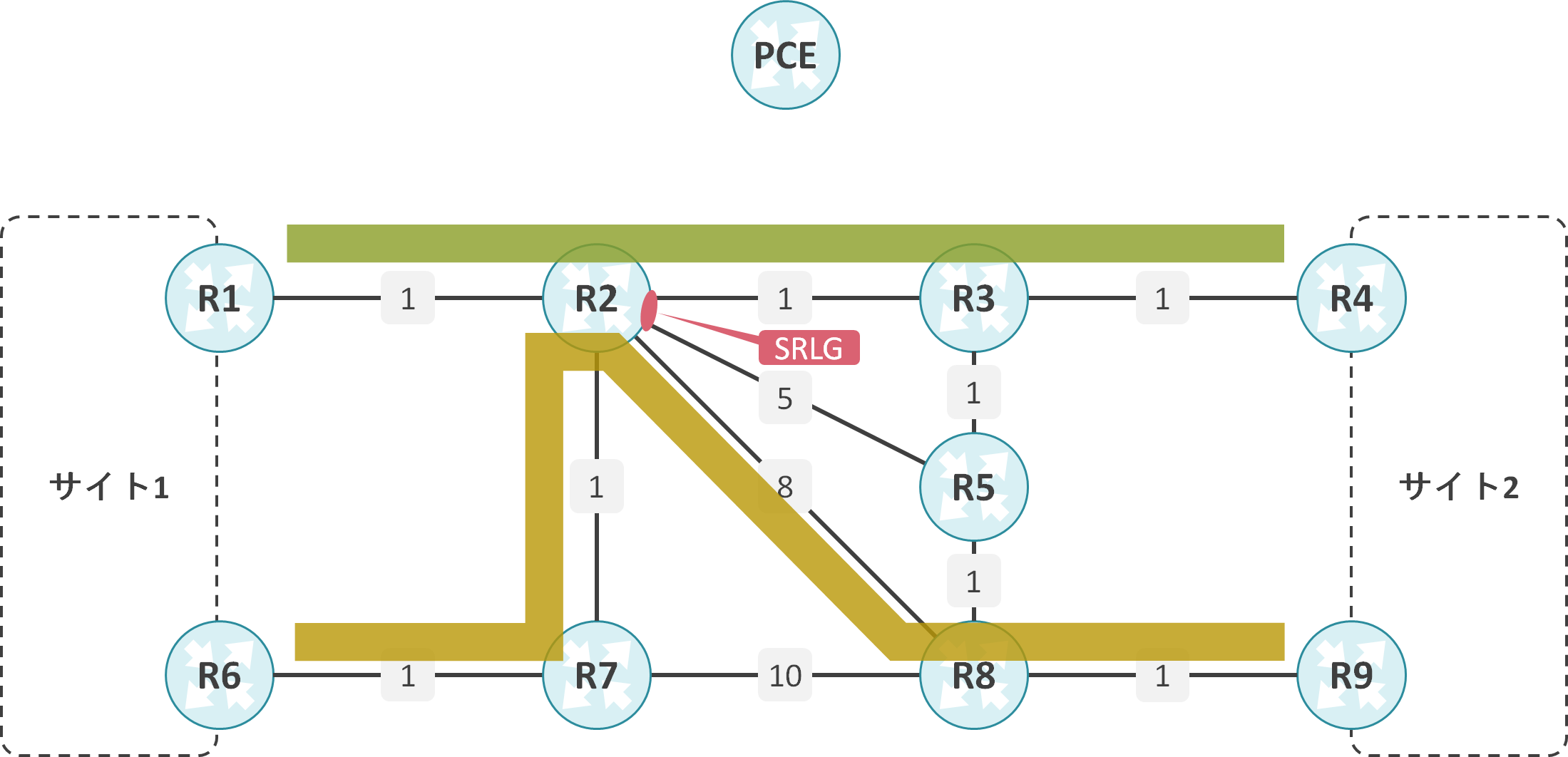
SRLG TypeのDisjoint Pathについて
Disjoint Pathではリンクとノードに加えて、既に計算済みのLSPが使用中のリンクと同じSRLGに所属しているリンクを経由しないように、新規のLSPを計算可能です。
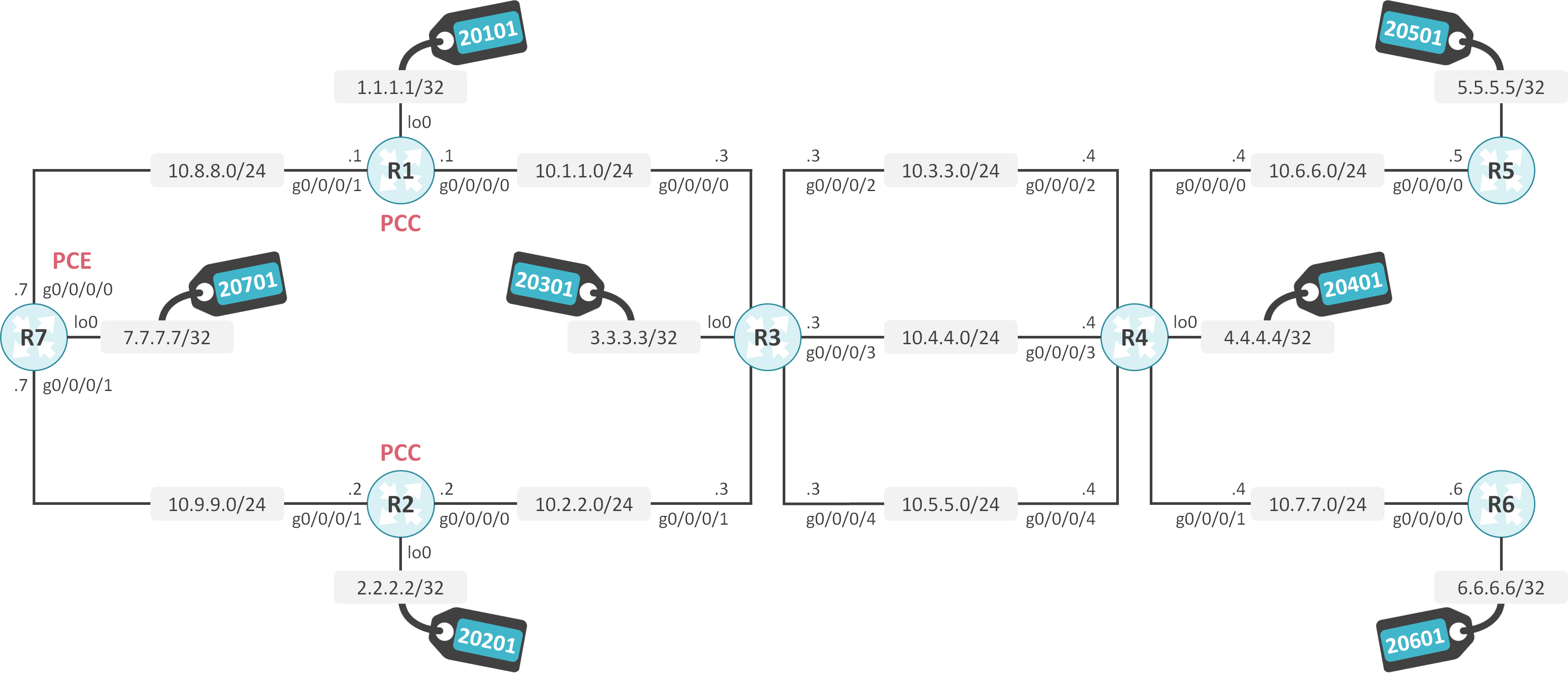
検証内容と設定
基本設定の内容
R1-R2-R3-R4-R5-R6-R7間でOSPF Area 0を構成します。
OSPFでSR-TEを有効にします。
R3-R4間の10.4.4.0/24のリンクのコストを30、10.5.5.0/24のリンクのコストを50に変更します。
R3のg0/0/0/2とg0/0/0/3にSRLGとして77を割り当てます。
R1でLoopback Interfaceの1.1.1.1/32にPrefix SIDとして20101を割り当てます。
R3でLoopback Interfaceの2.2.2.2/32にPrefix SIDとして20201を割り当てます。
R3でLoopback Interfaceの3.3.3.3/32にPrefix SIDとして20301を割り当てます。
R4でLoopback Interfaceの4.4.4.4/32にPrefix SIDとして20401を割り当てます。
R5でLoopback Interfaceの5.5.5.5/32にPrefix SIDとして20501を割り当てます。
R6でLoopback Interfaceの6.6.6.6/32にPrefix SIDとして20601を割り当てます。
R7でLoopback Interfaceの7.7.7.7/32にPrefix SIDとして20701を割り当てます。
R7をPCE、R1とR2をPCCとして動作させます。
初期設定
interface Loopback0
 ipv4 address 1.1.1.1 255.255.255.255
!
interface GigabitEthernet0/0/0/0
 ipv4 address 10.1.1.1 255.255.255.0
!
interface GigabitEthernet0/0/0/1
 ipv4 address 10.8.8.1 255.255.255.0
!
router ospf 1
 router-id 1.1.1.1
 segment-routing mpls
 area 0
  mpls traffic-eng
  interface Loopback0
   prefix-sid absolute 20101
  !
  interface GigabitEthernet0/0/0/0
   network point-to-point
  !
  interface GigabitEthernet0/0/0/1
   network point-to-point
  !
 !
!
segment-routing
 traffic-eng
  pcc
   pce address ipv4 7.7.7.7
interface Loopback0
 ipv4 address 2.2.2.2 255.255.255.255
!
interface GigabitEthernet0/0/0/0
 ipv4 address 10.2.2.2 255.255.255.0
!
interface GigabitEthernet0/0/0/1
 ipv4 address 10.9.9.2 255.255.255.0
!
router ospf 1
 router-id 2.2.2.2
 segment-routing mpls
 area 0
  mpls traffic-eng
  interface Loopback0
   prefix-sid absolute 20201
  !
  interface GigabitEthernet0/0/0/0
   network point-to-point
  !
  interface GigabitEthernet0/0/0/1
   network point-to-point
  !
 !
!
segment-routing
 traffic-eng
  pcc
   pce address ipv4 7.7.7.7
srlg
 interface GigabitEthernet0/0/0/2
  name SRLG_1
 !
 interface GigabitEthernet0/0/0/3
  name SRLG_1
 !
 name SRLG_1 value 77
!
interface Loopback0
 ipv4 address 3.3.3.3 255.255.255.0
!
interface GigabitEthernet0/0/0/0
 ipv4 address 10.1.1.3 255.255.255.0
!
interface GigabitEthernet0/0/0/1
 ipv4 address 10.2.2.3 255.255.255.0
!
interface GigabitEthernet0/0/0/2
 ipv4 address 10.3.3.3 255.255.255.0
!
interface GigabitEthernet0/0/0/3
 ipv4 address 10.4.4.3 255.255.255.0
!
interface GigabitEthernet0/0/0/4
 ipv4 address 10.5.5.3 255.255.255.0
!
router ospf 1
 router-id 3.3.3.3
 segment-routing mpls
 area 0
  mpls traffic-eng
  interface Loopback0
   prefix-sid absolute 20301
  !
  interface GigabitEthernet0/0/0/0
   network point-to-point
  !
  interface GigabitEthernet0/0/0/1
   network point-to-point
  !
  interface GigabitEthernet0/0/0/2
   network point-to-point
  !
  interface GigabitEthernet0/0/0/3
   cost 30
   network point-to-point
  !
  interface GigabitEthernet0/0/0/4
   cost 50
   network point-to-point
  !
 !
!
segment-routing
 traffic-eng
interface Loopback0
 ipv4 address 4.4.4.4 255.255.255.255
!
interface GigabitEthernet0/0/0/0
 ipv4 address 10.6.6.4 255.255.255.0
!
interface GigabitEthernet0/0/0/1
 ipv4 address 10.7.7.4 255.255.255.0
!
interface GigabitEthernet0/0/0/2
 ipv4 address 10.3.3.4 255.255.255.0
!
interface GigabitEthernet0/0/0/3
 ipv4 address 10.4.4.4 255.255.255.0
!
interface GigabitEthernet0/0/0/4
 ipv4 address 10.5.5.4 255.255.255.0
!
router ospf 1
 router-id 4.4.4.4
 segment-routing mpls
 area 0
  mpls traffic-eng
  interface Loopback0
   prefix-sid absolute 20401
  !
  interface GigabitEthernet0/0/0/0
   network point-to-point
  !
  interface GigabitEthernet0/0/0/1
   network point-to-point
  !
  interface GigabitEthernet0/0/0/2
   network point-to-point
  !
  interface GigabitEthernet0/0/0/3
   cost 30
   network point-to-point
  !
  interface GigabitEthernet0/0/0/4
   cost 50
   network point-to-point
  !
 !
!
segment-routing
 traffic-eng
interface Loopback0
 ipv4 address 5.5.5.5 255.255.255.255
!
interface GigabitEthernet0/0/0/0
 ipv4 address 10.6.6.5 255.255.255.0
!
router ospf 1
 router-id 5.5.5.5
 segment-routing mpls
 area 0
  mpls traffic-eng
  interface Loopback0
   prefix-sid absolute 20501
  !
  interface GigabitEthernet0/0/0/0
   network point-to-point
  !
 !
!
segment-routing
 traffic-eng
interface Loopback0
 ipv4 address 6.6.6.6 255.255.255.255
!
interface GigabitEthernet0/0/0/0
 ipv4 address 10.7.7.6 255.255.255.0
!
router ospf 1
 router-id 6.6.6.6
 segment-routing mpls
 area 0
  mpls traffic-eng
  interface Loopback0
   prefix-sid absolute 20601
  !
  interface GigabitEthernet0/0/0/0
   network point-to-point
  !
 !
!
segment-routing
 traffic-eng
pce
 address ipv4 7.7.7.7
!
interface Loopback0
 ipv4 address 7.7.7.7 255.255.255.255
!
interface GigabitEthernet0/0/0/0
 ipv4 address 10.8.8.7 255.255.255.0
!
interface GigabitEthernet0/0/0/1
 ipv4 address 10.9.9.7 255.255.255.0
!
router ospf 1
 distribute link-state
 router-id 7.7.7.7
 segment-routing mpls
 area 0
  mpls traffic-eng
  interface Loopback0
   prefix-sid absolute 20701
  !
  interface GigabitEthernet0/0/0/0
   network point-to-point
  !
  interface GigabitEthernet0/0/0/1
   network point-to-point
  !
 !
!
segment-routing
 traffic-eng
SRLGの設定と状態確認
SRLGの設定
最初にname <srlg-name> value <srlg-value>コマンドを使用してSRLGの名前と値を定義します。そして、インタフェースに対して、name <srlg-name>コマンドを設定し、SRLGを割り当てます。
srlg
 interface GigabitEthernet0/0/0/2
  name SRLG_1
 !
 interface GigabitEthernet0/0/0/3
  name SRLG_1
 !
 name SRLG_1 value 77
SRLGの状態確認
インタフェースに割り当てられたSRLGはshow srlgコマンドで確認可能です。
RP/0/RP0/CPU0:R3#show srlg

  System Information::
  Interface Count          : 5 (Maximum Interfaces Supported 512)
  Group Count              : 0 (Maximum Groups Supported 50)
  Inherit Location Count   : 0 (Maximum Inherit Locations Supported 10)
  Optical Interfaces Count : 0 (Maximum Optical Interfaces Supported 500)

  Interface    : GigabitEthernet0/0/0/0, Value Count : 0
  References   : 2, Internal flags : 0x2

  Interface    : GigabitEthernet0/0/0/1, Value Count : 0
  References   : 2, Internal flags : 0x2

  Interface    : GigabitEthernet0/0/0/2, Value Count : 1
  References   : 3, Internal flags : 0x3
  SRLG Values  : 77

  Interface    : GigabitEthernet0/0/0/3, Value Count : 1
  References   : 3, Internal flags : 0x3
  SRLG Values  : 77

  Interface    : GigabitEthernet0/0/0/4, Value Count : 0
  References   : 2, Internal flags : 0x2
OSPFの状態確認
R3のg0/0/0/2のOSPFの状態を見ると、OSPFがSRLGを認識していることが確認できます。
RP/0/RP0/CPU0:R3#show ospf interface GigabitEthernet0/0/0/2

GigabitEthernet0/0/0/2 is up, line protocol is up
  Internet Address 10.3.3.3/24, Area 0, SID 0, Strict-SPF SID 0
  Label stack Primary label 1 Backup label 3 SRTE label 10
  Process ID 1, Router ID 3.3.3.3, Network Type POINT_TO_POINT, Cost: 1
  Transmit Delay is 1 sec, State POINT_TO_POINT, MTU 1500, MaxPktSz 1500
  Forward reference No, Unnumbered no,  Bandwidth 1000000
  Timer intervals configured, Hello 10, Dead 40, Wait 40, Retransmit 5
    Hello due in 00:00:09:323
  Index 4/4, flood queue length 0
  Next 0(0)/0(0)
  Last flood scan length is 1, maximum is 1
  Last flood scan time is 0 msec, maximum is 0 msec
  LS Ack List: current length 0, high water mark 6
  Neighbor Count is 1, Adjacent neighbor count is 1
    Adjacent with neighbor 4.4.4.4
  Suppress hello for 0 neighbor(s)
  Multi-area interface Count is 0
  SRLG values:
    77
R3の10.3.3.0/24のリンクのMPLS Traffic Engineering LSAを見ると、SRLGが格納されていることが確認できます。
RP/0/RP0/CPU0:R3#show ospf database opaque-area 1.0.0.9 adv-router 3.3.3.3


            OSPF Router with ID (3.3.3.3) (Process ID 1)

                Type-10 Opaque Link Area Link States (Area 0)

  LS age: 508
  Options: (No TOS-capability, DC)
  LS Type: Opaque Area Link
  Link State ID: 1.0.0.9
  Opaque Type: 1
  Opaque ID: 9
  Advertising Router: 3.3.3.3
  LS Seq Number: 80000002
  Checksum: 0xde91
  Length: 212

    Link connected to Point-to-Point network
      Link ID : 4.4.4.4
      (all bandwidths in bytes/sec)
      Interface Address : 10.3.3.3
      Neighbor Address : 10.3.3.4
      Admin Metric : 1
      Maximum bandwidth : 125000000
      Maximum reservable bandwidth global: 0
      Number of Priority : 8
      Priority 0 :                    0  Priority 1 :                    0
      Priority 2 :                    0  Priority 3 :                    0
      Priority 4 :                    0  Priority 5 :                    0
      Priority 6 :                    0  Priority 7 :                    0
      Affinity Bit : 0
      IGP Metric : 1
      GMPLS Shared Risked Link Group : Length: 4
        Number of SRLGs (1)
        [1]: 77
      Extended Administrative Group : Length: 8
       EAG[0]: 0
       EAG[1]: 0
       EAG[2]: 0
       EAG[3]: 0
       EAG[4]: 0
       EAG[5]: 0
       EAG[6]: 0
       EAG[7]: 0

    Number of Links : 1
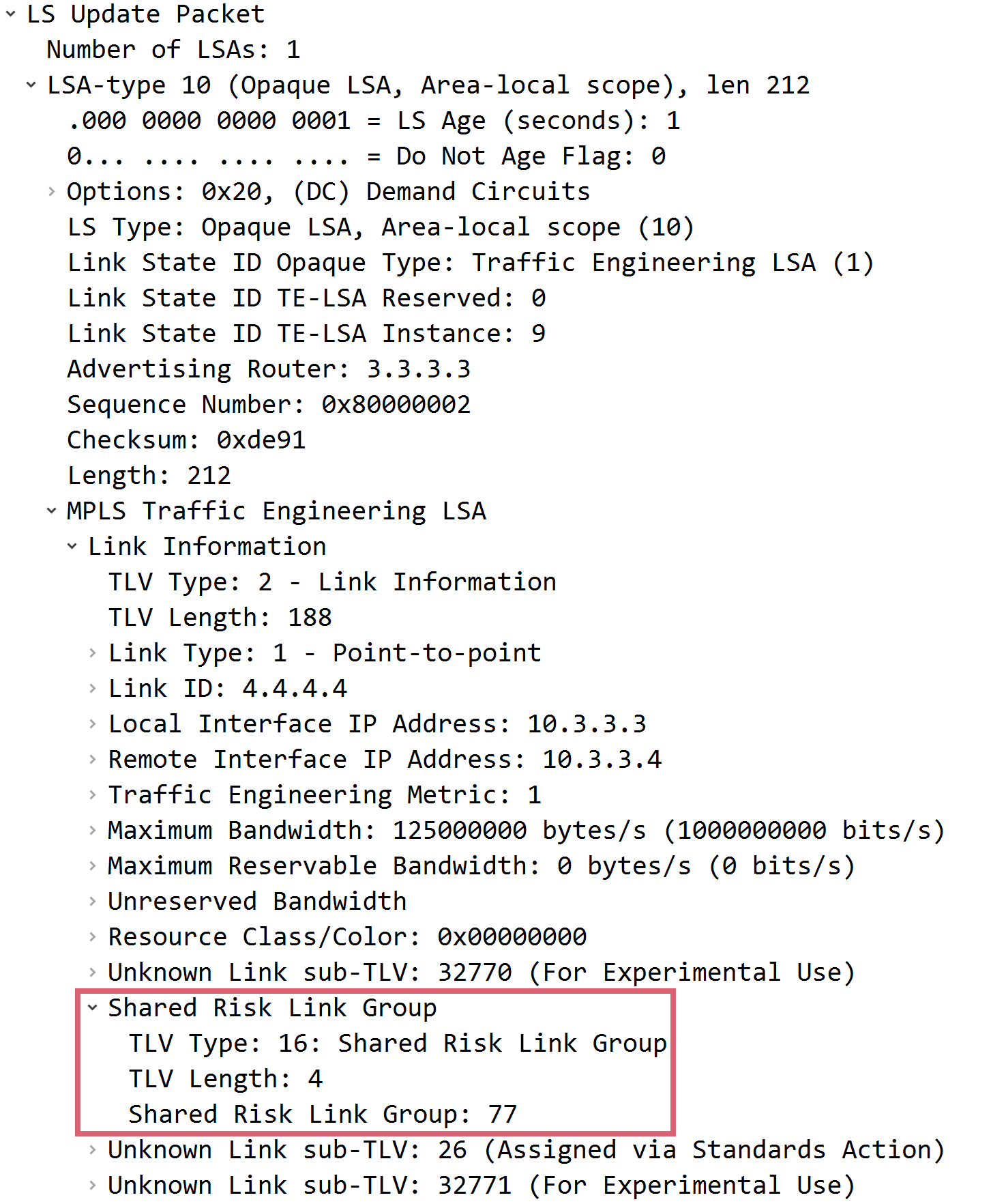
以下はR3の10.3.3.0/24のリンクのMPLS Traffic Engineering LSAのキャプチャになります。SRLGが格納されていることが確認できます。
SR-TE DBの状態確認
R7のSR-TE DB内を見ると、R3の10.3.3.0/24と10.4.4.0/24のリンクにSRLGが割り当てられていることが確認できます。
RP/0/RP0/CPU0:R7#show pce ipv4 topology traffic-eng 3.3.3.3

PCE's topology database - detail:
---------------------------------
Node 2
  .
  <一部省略>
  .
  Link[2]: local address 10.3.3.3, remote address 10.3.3.4
    Local node:
      OSPF router ID: 3.3.3.3 area ID: 0 ASN: 0
    Remote node:
      TE router ID: 4.4.4.4
      OSPF router ID: 4.4.4.4 area ID: 0 ASN: 0
    Metric: IGP 1, TE 1, Latency 1 microseconds
    Bandwidth: Total 125000000 Bps, Reservable 0 Bps
    Admin-groups: 0x00000000
    Adj SID: 24002 (unprotected)
    SRLG Values: 77

  Link[3]: local address 10.4.4.3, remote address 10.4.4.4
    Local node:
      OSPF router ID: 3.3.3.3 area ID: 0 ASN: 0
    Remote node:
      TE router ID: 4.4.4.4
      OSPF router ID: 4.4.4.4 area ID: 0 ASN: 0
    Metric: IGP 30, TE 30, Latency 30 microseconds
    Bandwidth: Total 125000000 Bps, Reservable 0 Bps
    Admin-groups: 0x00000000
    Adj SID: 24003 (unprotected)
    SRLG Values: 77
    .
    <一部省略>
Disjoint Group設定無し
SR-TE Policyの設定
R1でEnd-pointに5.5.5.5、R2でEnd-pointに6.6.6.6を指定したSR-TE Policyを設定し、PCEにLSPの計算を依頼します。ただし、Disjoint Groupは設定しません。
segment-routing
 traffic-eng
  policy SR-TE_POLICY
   color 1 end-point ipv4 5.5.5.5
   autoroute
    include all
   !
   candidate-paths
    preference 10
     dynamic
      pcep
segment-routing
 traffic-eng
  policy SR-TE_POLICY
   color 1 end-point ipv4 6.6.6.6
   autoroute
    include all
   !
   candidate-paths
    preference 10
     dynamic
      pcep
PCEが計算したLSPの確認
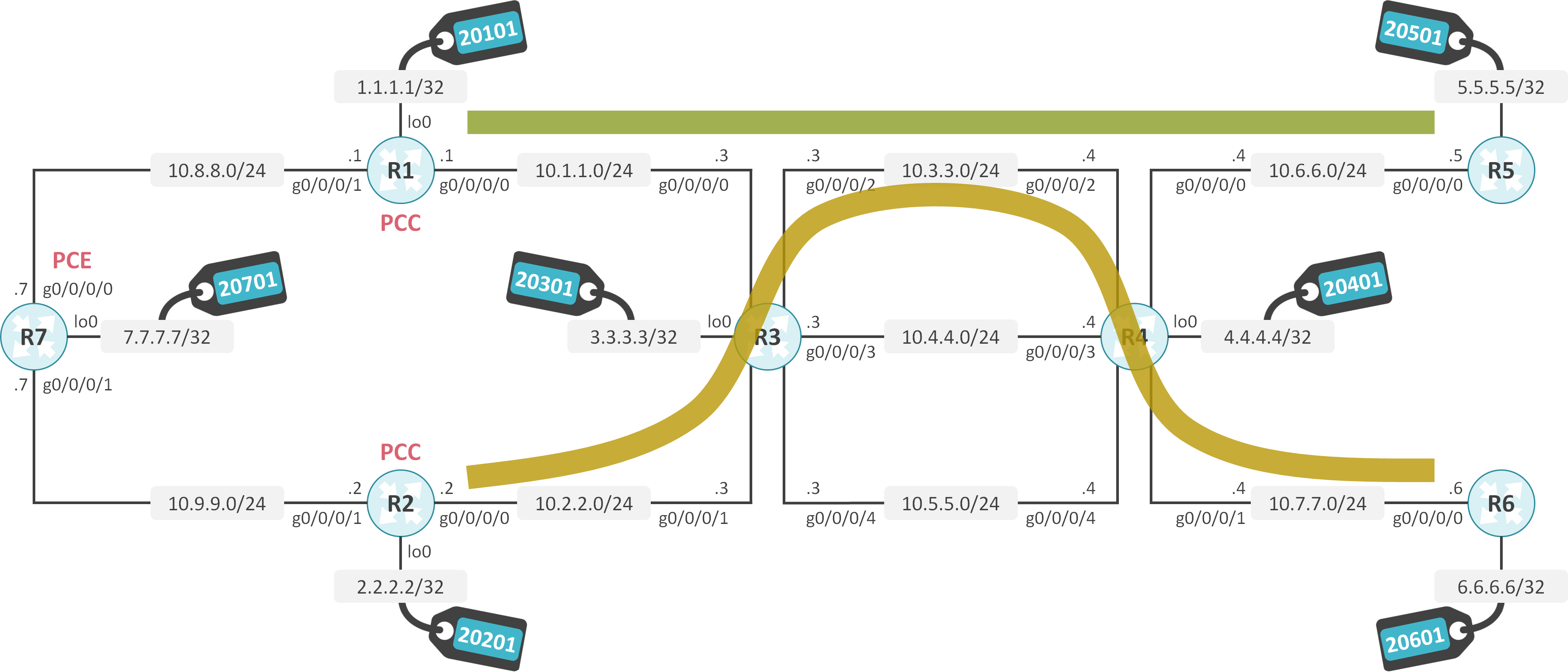
R7が計算したR1とR2のLSPを見ると、両方とも、R3-R4間の10.3.3.0/24のリンクを経由していることが確認できます。
RP/0/RP0/CPU0:R7#show pce lsp pcc ipv4 1.1.1.1 detail

PCE's tunnel database:
----------------------
PCC 1.1.1.1:

Tunnel Name: cfg_SR-TE_POLICY_discr_10
Color: 1
Interface Name: srte_c_1_ep_5.5.5.5
 LSPs:
  LSP[0]:
   source 1.1.1.1, destination 5.5.5.5, tunnel ID 1, LSP ID 1
   State: Admin up, Operation up
   Setup type: Segment Routing
   Binding SID: 24006
   Maximum SID Depth: 10
   Preference: 10
   Bandwidth: signaled 0 kbps, applied 0 kbps
   PCEP information:
     PLSP-ID 0x1, flags: D:1 S:0 R:0 A:1 O:1 C:0
   LSP Role: Single LSP
   State-sync PCE: None
   PCC: 1.1.1.1
   LSP is subdelegated to: None
   Reported path:
     Metric type: TE, Accumulated Metric 3
      SID[0]: Node, Label 20501, Address 5.5.5.5
   Computed path: (Local PCE)
     Computed Time: Sat Jun 27 19:46:14 UTC 2020 (00:02:01 ago)
     Metric type: TE, Accumulated Metric 3
      SID[0]: Node, Label 20501, Address 5.5.5.5
   Recorded path:
     None
   Disjoint Group Information:
     None
RP/0/RP0/CPU0:R7#show pce lsp pcc ipv4 2.2.2.2 detail

PCE's tunnel database:
----------------------
PCC 2.2.2.2:

Tunnel Name: cfg_SR-TE_POLICY_discr_10
Color: 1
Interface Name: srte_c_1_ep_6.6.6.6
 LSPs:
  LSP[0]:
   source 2.2.2.2, destination 6.6.6.6, tunnel ID 1, LSP ID 1
   State: Admin up, Operation up
   Setup type: Segment Routing
   Binding SID: 24006
   Maximum SID Depth: 10
   Preference: 10
   Bandwidth: signaled 0 kbps, applied 0 kbps
   PCEP information:
     PLSP-ID 0x1, flags: D:1 S:0 R:0 A:1 O:1 C:0
   LSP Role: Single LSP
   State-sync PCE: None
   PCC: 2.2.2.2
   LSP is subdelegated to: None
   Reported path:
     Metric type: TE, Accumulated Metric 3
      SID[0]: Node, Label 20601, Address 6.6.6.6
   Computed path: (Local PCE)
     Computed Time: Sat Jun 27 19:46:24 UTC 2020 (00:02:25 ago)
     Metric type: TE, Accumulated Metric 3
      SID[0]: Node, Label 20601, Address 6.6.6.6
   Recorded path:
     None
   Disjoint Group Information:
     None
疎通確認
R1の1.1.1.1からR5の5.5.5.5へTracerouteを実施します。
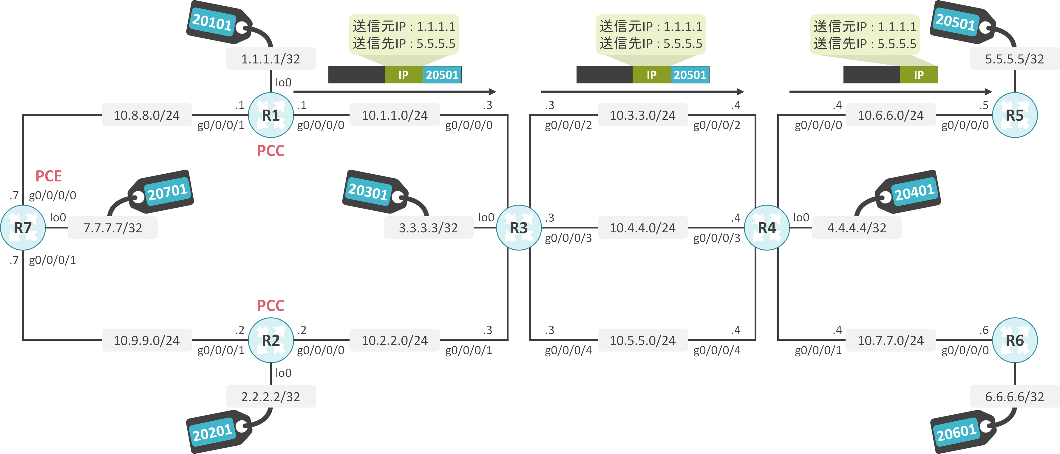
R1からR5へのトラフィックがR3-R4間の10.3.3.0/24のリンクを経由していることが確認できます。
RP/0/RP0/CPU0:R1#traceroute 5.5.5.5 source 1.1.1.1

Type escape sequence to abort.
Tracing the route to 5.5.5.5

 1  10.1.1.3 [MPLS: Label 20501 Exp 0] 116 msec  127 msec  104 msec
 2  10.3.3.4 [MPLS: Label 20501 Exp 0] 100 msec  96 msec  87 msec
 3  10.6.6.5 100 msec  *  123 msec
R2の2.2.2.2からR6の6.6.6.6へTracerouteを実施します。
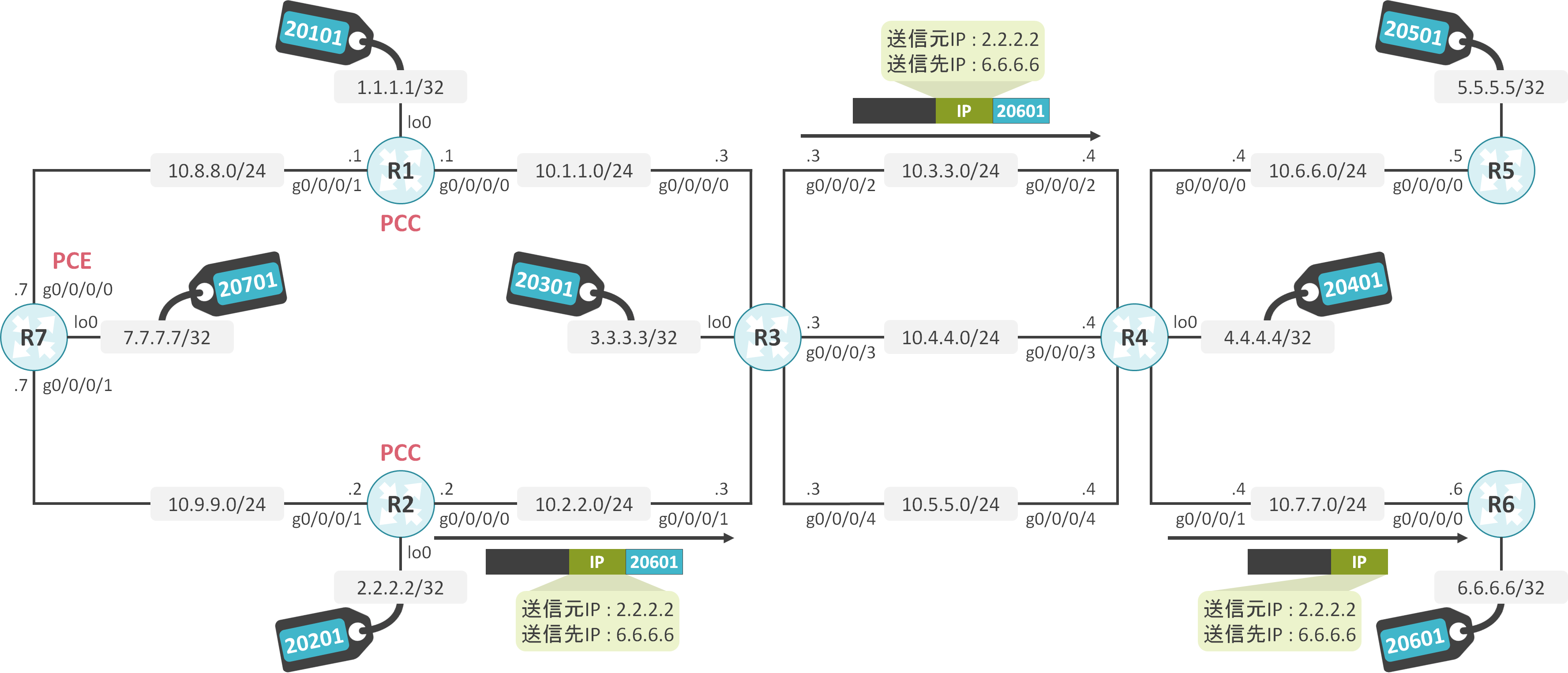
R2からR6へのトラフィックがR3-R4間の10.3.3.0/24のリンクを経由していることが確認できます。
RP/0/RP0/CPU0:R2#traceroute 6.6.6.6 source 2.2.2.2

Type escape sequence to abort.
Tracing the route to 6.6.6.6

 1  10.2.2.3 [MPLS: Label 20601 Exp 0] 198 msec  119 msec  158 msec
 2  10.3.3.4 [MPLS: Label 20601 Exp 0] 150 msec  147 msec  142 msec
 3  10.7.7.6 168 msec  *  170 msec
Disjoint Group設定有り
SR-TE Policyの設定
同じSRLGに属するリンクを経由させないDisjoint Groupはdisjoint-path group-id <group-id> type srlgコマンドで設定します。
segment-routing
 traffic-eng
  policy SR-TE_POLICY
   color 1 end-point ipv4 5.5.5.5
   autoroute
    include all
   !
   candidate-paths
    preference 10
     dynamic
      pcep
      !
     !
     constraints
      disjoint-path group-id 1 type srlg
segment-routing
 traffic-eng
  policy SR-TE_POLICY
   color 1 end-point ipv4 6.6.6.6
   autoroute
    include all
   !
   candidate-paths
    preference 10
     dynamic
      pcep
      !
     !
     constraints
      disjoint-path group-id 1 type srlg
PCEが計算したLSPの確認
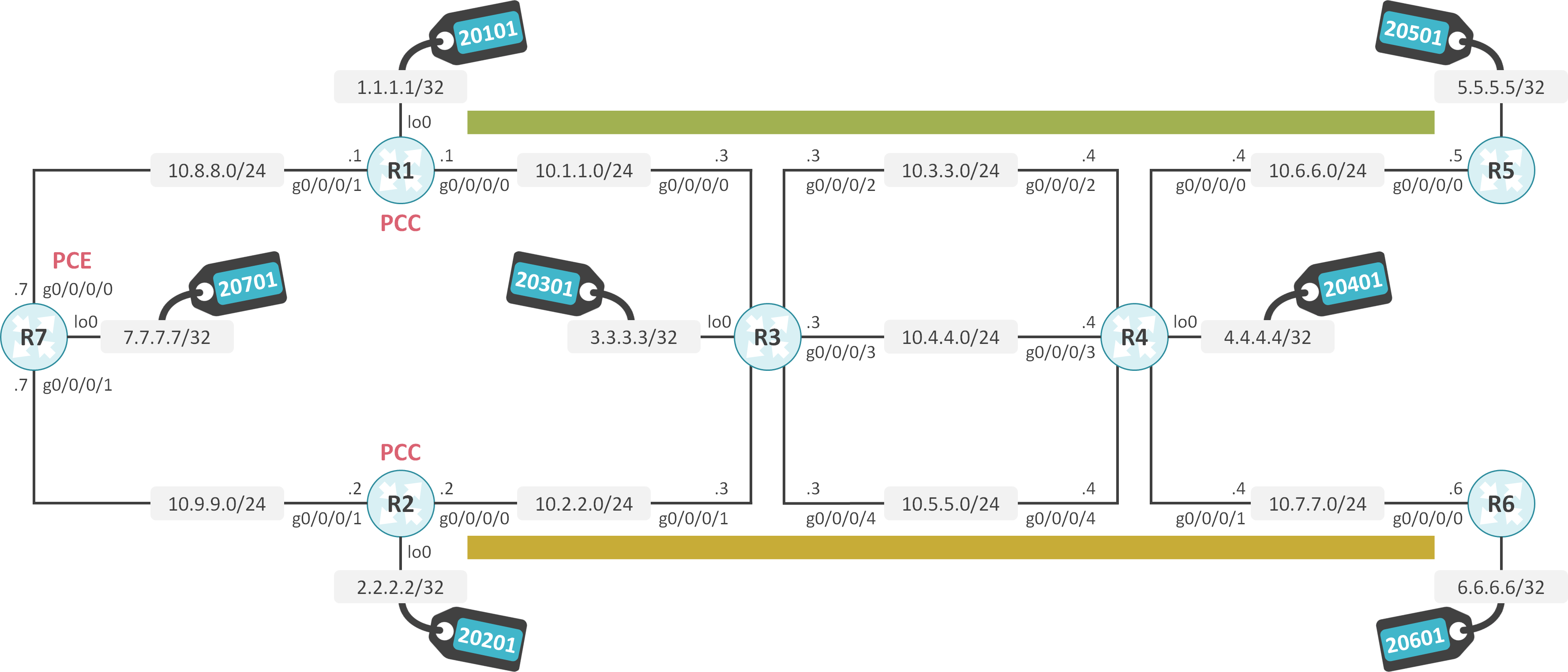
R7が計算したR1とR2のLSPを見ると、R1のLSPはR3-R4間の10.3.3.0/24のリンク、R2のLSPはR3-R4間の10.5.5.0/24のリンクを経由していることが確認できます。
RP/0/RP0/CPU0:R7#show pce lsp pcc ipv4 1.1.1.1 detail

PCE's tunnel database:
----------------------
PCC 1.1.1.1:

Tunnel Name: cfg_SR-TE_POLICY_discr_10
Color: 1
Interface Name: srte_c_1_ep_5.5.5.5
 LSPs:
  LSP[0]:
   source 1.1.1.1, destination 5.5.5.5, tunnel ID 6, LSP ID 1
   State: Admin up, Operation up
   Setup type: Segment Routing
   Binding SID: 24021
   Maximum SID Depth: 10
   Preference: 10
   Bandwidth: signaled 0 kbps, applied 0 kbps
   PCEP information:
     PLSP-ID 0x6, flags: D:1 S:0 R:0 A:1 O:1 C:0
   LSP Role: Exclude LSP
   State-sync PCE: None
   PCC: 1.1.1.1
   LSP is subdelegated to: None
   Reported path:
     Metric type: TE, Accumulated Metric 3
      SID[0]: Node, Label 20501, Address 5.5.5.5
   Computed path: (Local PCE)
     Computed Time: Sat Jun 27 20:49:48 UTC 2020 (00:00:12 ago)
     Metric type: TE, Accumulated Metric 3
      SID[0]: Node, Label 20501, Address 5.5.5.5
   Recorded path:
     None
   Disjoint Group Information:
     Type SRLG-Disjoint, Group 1
RP/0/RP0/CPU0:R7#show pce lsp pcc ipv4 2.2.2.2 detail

PCE's tunnel database:
----------------------
PCC 2.2.2.2:

Tunnel Name: cfg_SR-TE_POLICY_discr_10
Color: 1
Interface Name: srte_c_1_ep_6.6.6.6
 LSPs:
  LSP[0]:
   source 2.2.2.2, destination 6.6.6.6, tunnel ID 6, LSP ID 1
   State: Admin up, Operation up
   Setup type: Segment Routing
   Binding SID: 24016
   Maximum SID Depth: 10
   Preference: 10
   Bandwidth: signaled 0 kbps, applied 0 kbps
   PCEP information:
     PLSP-ID 0x6, flags: D:1 S:0 R:0 A:1 O:1 C:0
   LSP Role: Disjoint LSP
   State-sync PCE: None
   PCC: 2.2.2.2
   LSP is subdelegated to: None
   Reported path:
     Metric type: TE, Accumulated Metric 52
      SID[0]: Node, Label 20301, Address 3.3.3.3
      SID[1]: Adj, Label 24004, Address: local 10.5.5.3 remote 10.5.5.4
      SID[2]: Node, Label 20601, Address 6.6.6.6
   Computed path: (Local PCE)
     Computed Time: Sat Jun 27 20:49:48 UTC 2020 (00:00:23 ago)
     Metric type: TE, Accumulated Metric 52
      SID[0]: Node, Label 20301, Address 3.3.3.3
      SID[1]: Adj, Label 24004, Address: local 10.5.5.3 remote 10.5.5.4
      SID[2]: Node, Label 20601, Address 6.6.6.6
   Recorded path:
     None
   Disjoint Group Information:
     Type SRLG-Disjoint, Group 1
疎通確認
R1の1.1.1.1からR5の5.5.5.5へTracerouteを実施します。

R1からR5へのトラフィックがR3-R4間の10.3.3.0/24のリンクを経由していることが確認できます。
RP/0/RP0/CPU0:R1#traceroute 5.5.5.5 source 1.1.1.1

Type escape sequence to abort.
Tracing the route to 5.5.5.5

 1  10.1.1.3 [MPLS: Label 20501 Exp 0] 116 msec  127 msec  104 msec
 2  10.3.3.4 [MPLS: Label 20501 Exp 0] 100 msec  96 msec  87 msec
 3  10.6.6.5 100 msec  *  123 msec
R2の2.2.2.2からR6の6.6.6.6へTracerouteを実施します。
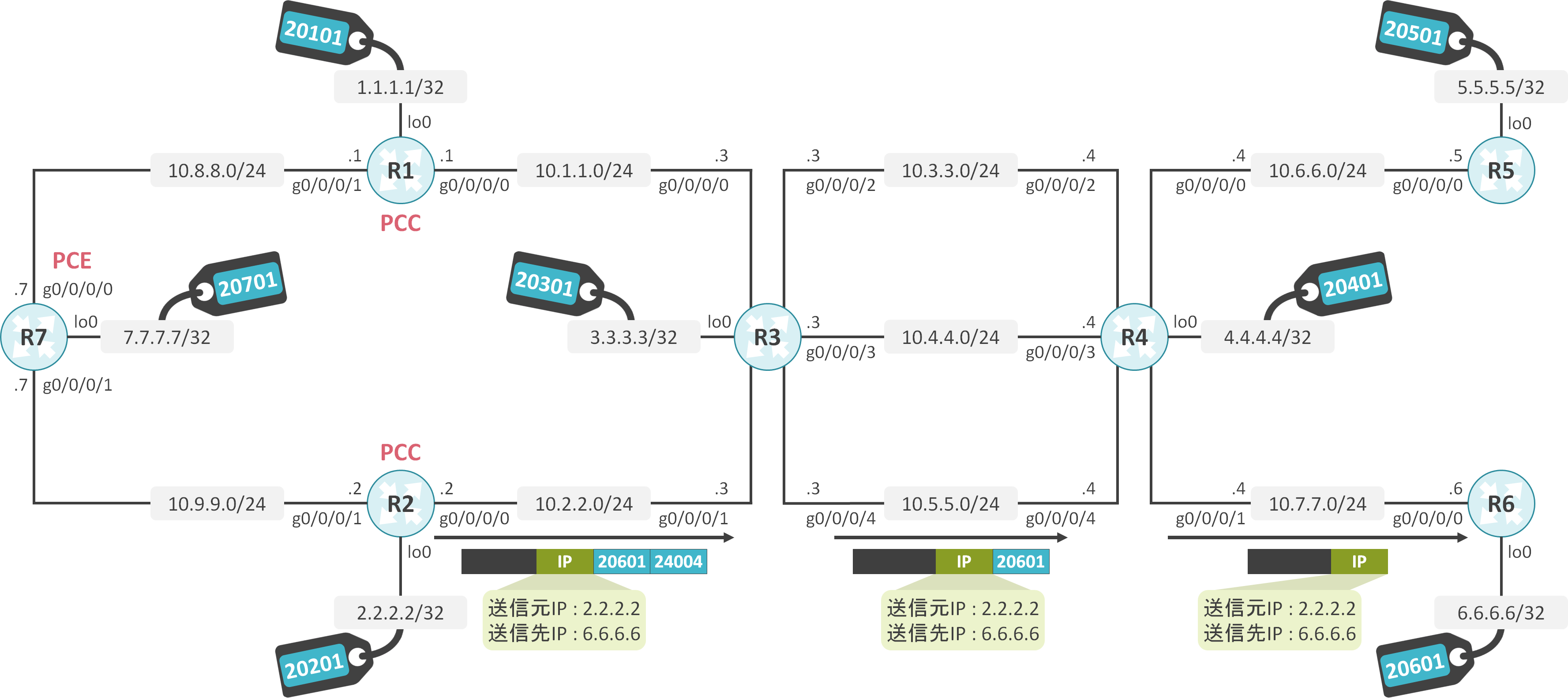
R2からR6へのトラフィックがR3-R4間の10.5.5.0/24のリンクを経由していることが確認できます。
RP/0/RP0/CPU0:R2#traceroute 6.6.6.6 source 2.2.2.2

Type escape sequence to abort.
Tracing the route to 6.6.6.6

 1  10.2.2.3 [MPLS: Labels 24004/20601 Exp 0] 84 msec  87 msec  105 msec
 2  10.5.5.4 [MPLS: Label 20601 Exp 0] 131 msec  106 msec  163 msec
 3  10.7.7.6 98 msec  *  72 msec


コメント