今回はOSPFのDemand Circuitと呼ばれる機能について解説します。
座学
Demand Circuit
Flood Reductionでは、定期的なLSUパケットの送信は抑制可能ですが、Helloパケットは定期的に送信され続けます。
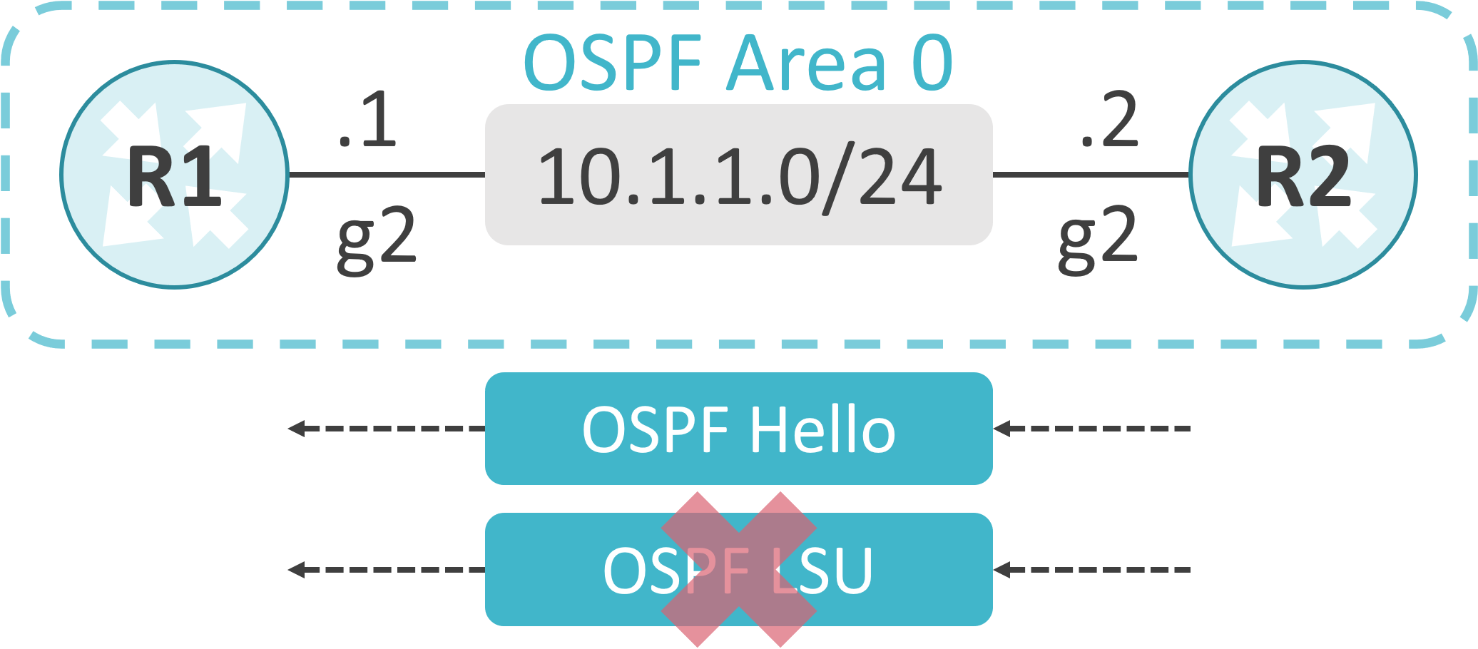
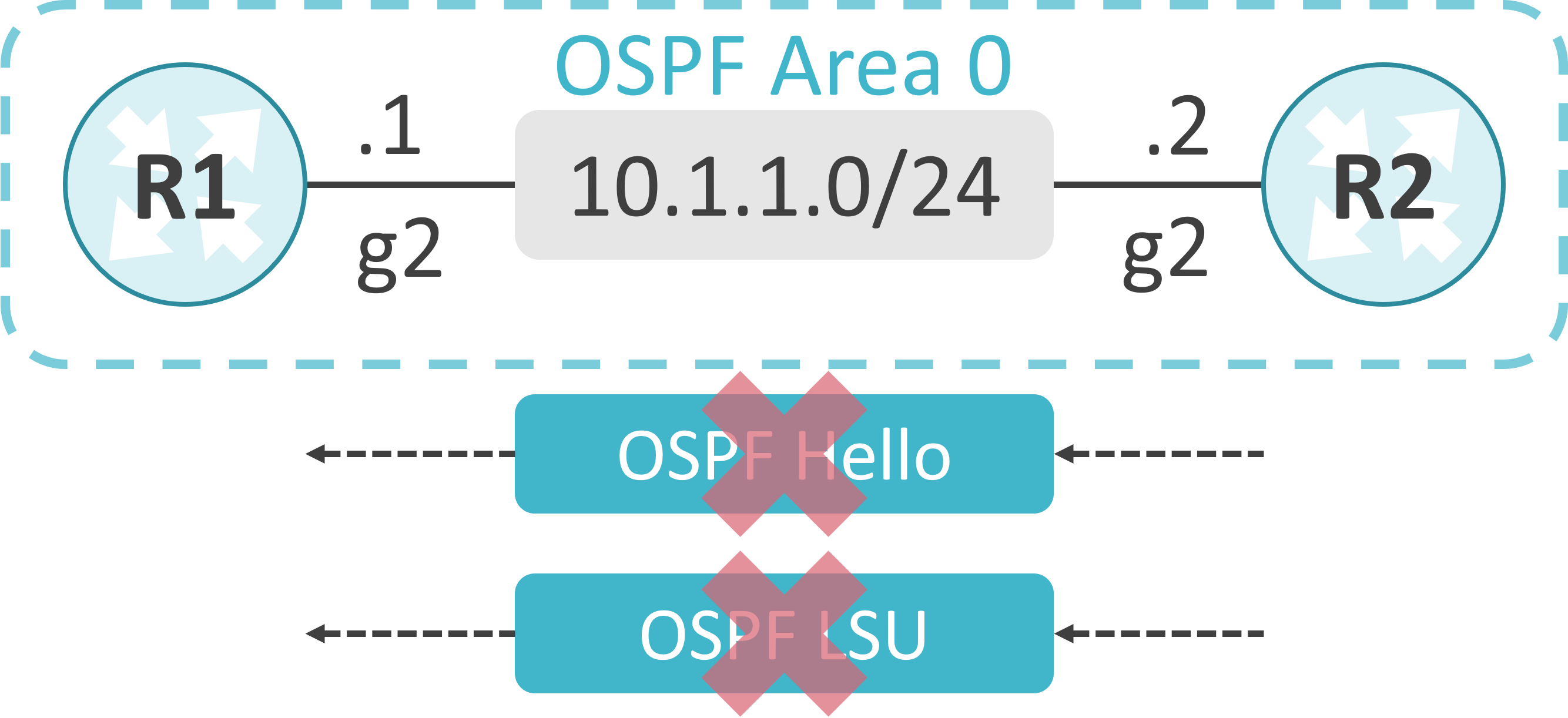
Demand Circuitを使用することで、定期的なLSUパケットの抑制に加え、定期的なHelloパケットの抑制も可能です。
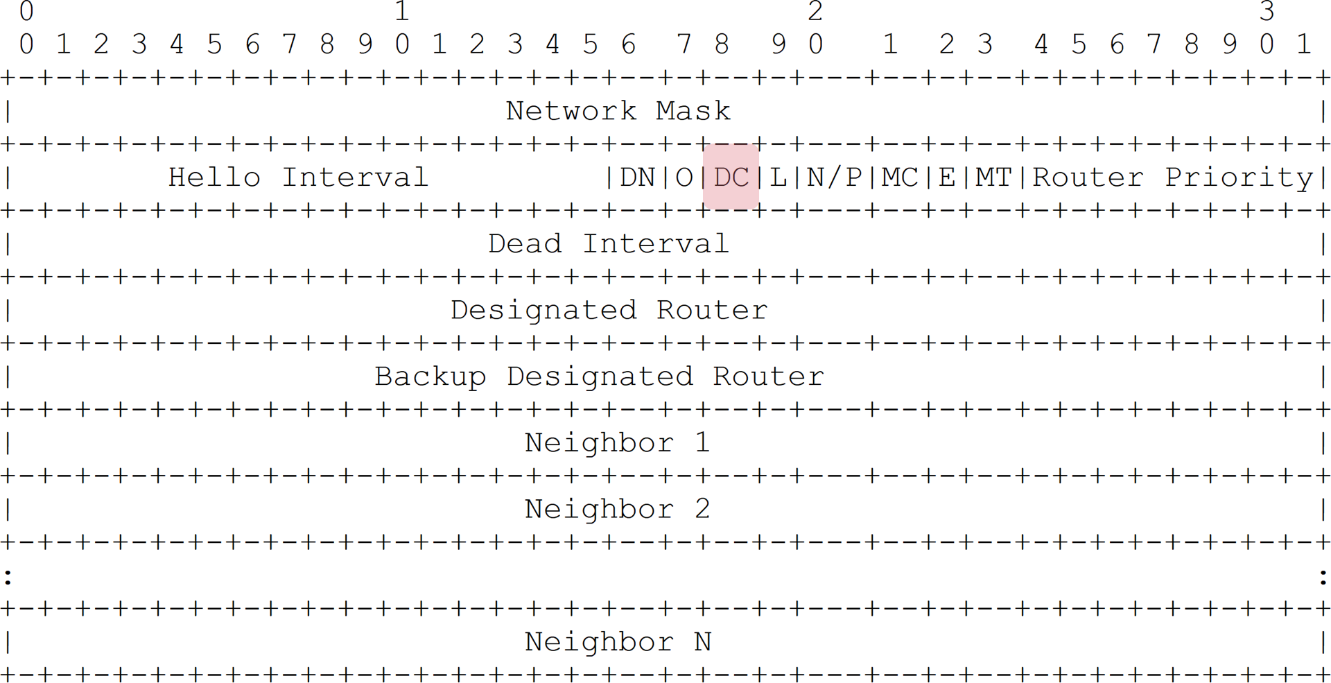
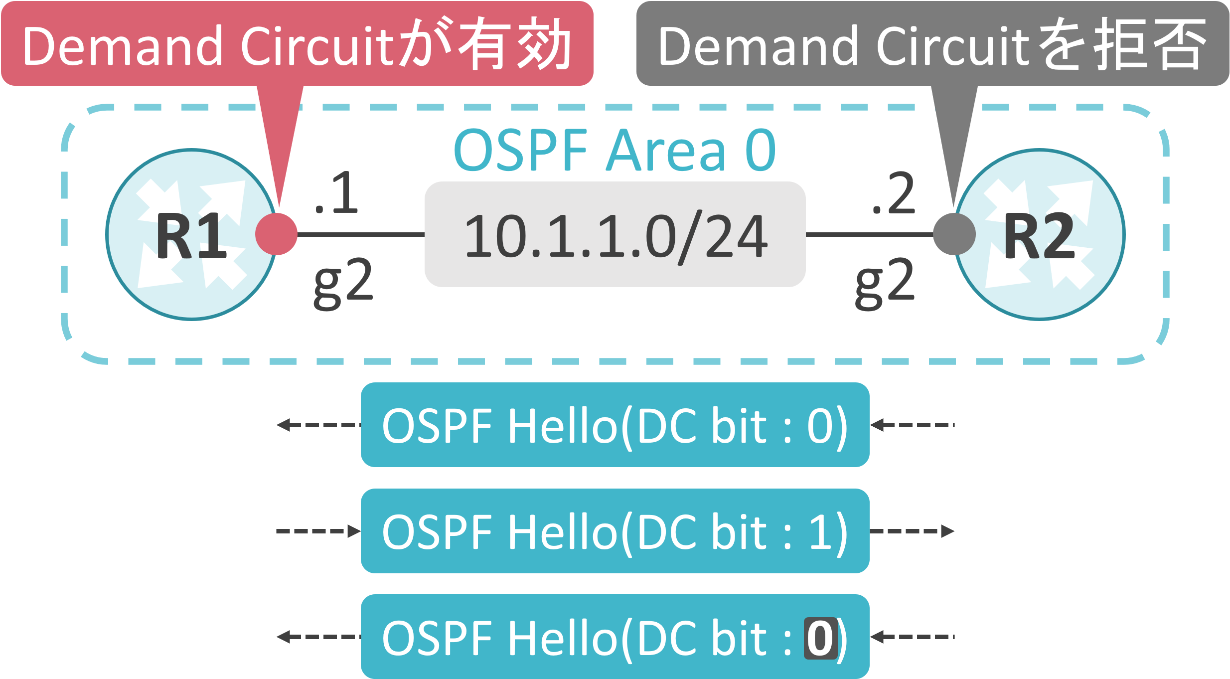
Demand Circuitが有効な場合、HelloパケットのDC(Demand Circuit) bitに1がセットされます。
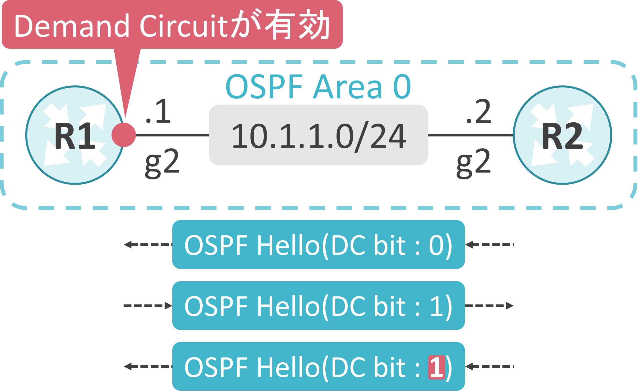
下図の様に、R1でのみDemand Circuitが有効な場合、R2はDC bitが1にセットされたHelloパケットを受信後、R2はHelloパケットを送信する際、DC bitに1をセットするようになります。この結果、R1とR2でDemand Circuitが有効になります。
下図の様に、R2にはDemand Circuitを拒否する設定が投入されている場合、R2はDC bitが1にセットされたHelloパケットを受信後、R2はDC bitが0のHelloパケットを送信し続けます。この結果、R1でのみDemand Circuitが有効になり、R2ではDemand Circuitが無効のままになります。
実機での動作確認
検証内容
R1のg2、R2のg2でOSPF Area 0を有効にします。
Network TypeにはPoint-to-Pointを使用します。
Demand Circuitを有効にした際の動作を確認します。

初期設定
interface GigabitEthernet2
 ip address 10.1.1.1 255.255.255.0
 ip ospf network point-to-point
!
router ospf 1
 router-id 1.1.1.1
 network 10.1.1.0 0.0.0.255 area 0
interface GigabitEthernet2
 ip address 10.1.1.2 255.255.255.0
 ip ospf network point-to-point
!
router ospf 1
 router-id 2.2.2.2
 network 10.1.1.0 0.0.0.255 area 0
Demand Circuit設定前
OSPFが動作しているインタフェースの状態確認
R1のg2でDemand Circuitが無効なことが確認できます。
R1#show ip ospf interface
GigabitEthernet2 is up, line protocol is up
  Internet Address 10.1.1.1/24, Interface ID 6, Area 0
  Attached via Network Statement
  Process ID 1, Router ID 1.1.1.1, Network Type POINT_TO_POINT, Cost: 1
  Topology-MTID    Cost    Disabled    Shutdown      Topology Name
        0           1         no          no            Base
  Transmit Delay is 1 sec, State POINT_TO_POINT
  Timer intervals configured, Hello 10, Dead 40, Wait 40, Retransmit 5
    oob-resync timeout 40
    Hello due in 00:00:02
  Supports Link-local Signaling (LLS)
  Cisco NSF helper support enabled
  IETF NSF helper support enabled
  Index 1/1/1, flood queue length 0
  Next 0x0(0)/0x0(0)/0x0(0)
  Last flood scan length is 1, maximum is 1
  Last flood scan time is 0 msec, maximum is 0 msec
  Neighbor Count is 1, Adjacent neighbor count is 1
    Adjacent with neighbor 2.2.2.2
  Suppress hello for 0 neighbor(s)
R2のg2でDemand Circuitが無効なことが確認できます。
R2#show ip ospf interface
GigabitEthernet2 is up, line protocol is up
  Internet Address 10.1.1.2/24, Interface ID 6, Area 0
  Attached via Network Statement
  Process ID 1, Router ID 2.2.2.2, Network Type POINT_TO_POINT, Cost: 1
  Topology-MTID    Cost    Disabled    Shutdown      Topology Name
        0           1         no          no            Base
  Transmit Delay is 1 sec, State POINT_TO_POINT
  Timer intervals configured, Hello 10, Dead 40, Wait 40, Retransmit 5
    oob-resync timeout 40
    Hello due in 00:00:00
  Supports Link-local Signaling (LLS)
  Cisco NSF helper support enabled
  IETF NSF helper support enabled
  Index 1/1/1, flood queue length 0
  Next 0x0(0)/0x0(0)/0x0(0)
  Last flood scan length is 1, maximum is 1
  Last flood scan time is 0 msec, maximum is 0 msec
  Neighbor Count is 1, Adjacent neighbor count is 1
    Adjacent with neighbor 1.1.1.1
  Suppress hello for 0 neighbor(s)
Helloパケットの確認
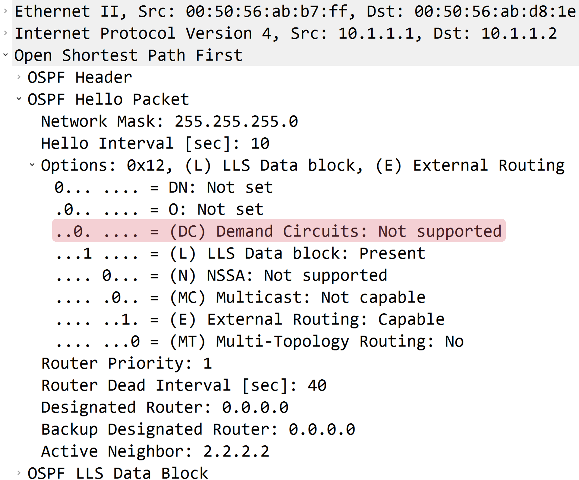
R1が送信したHelloパケットのDC bitに0がセットされていることが確認できます。
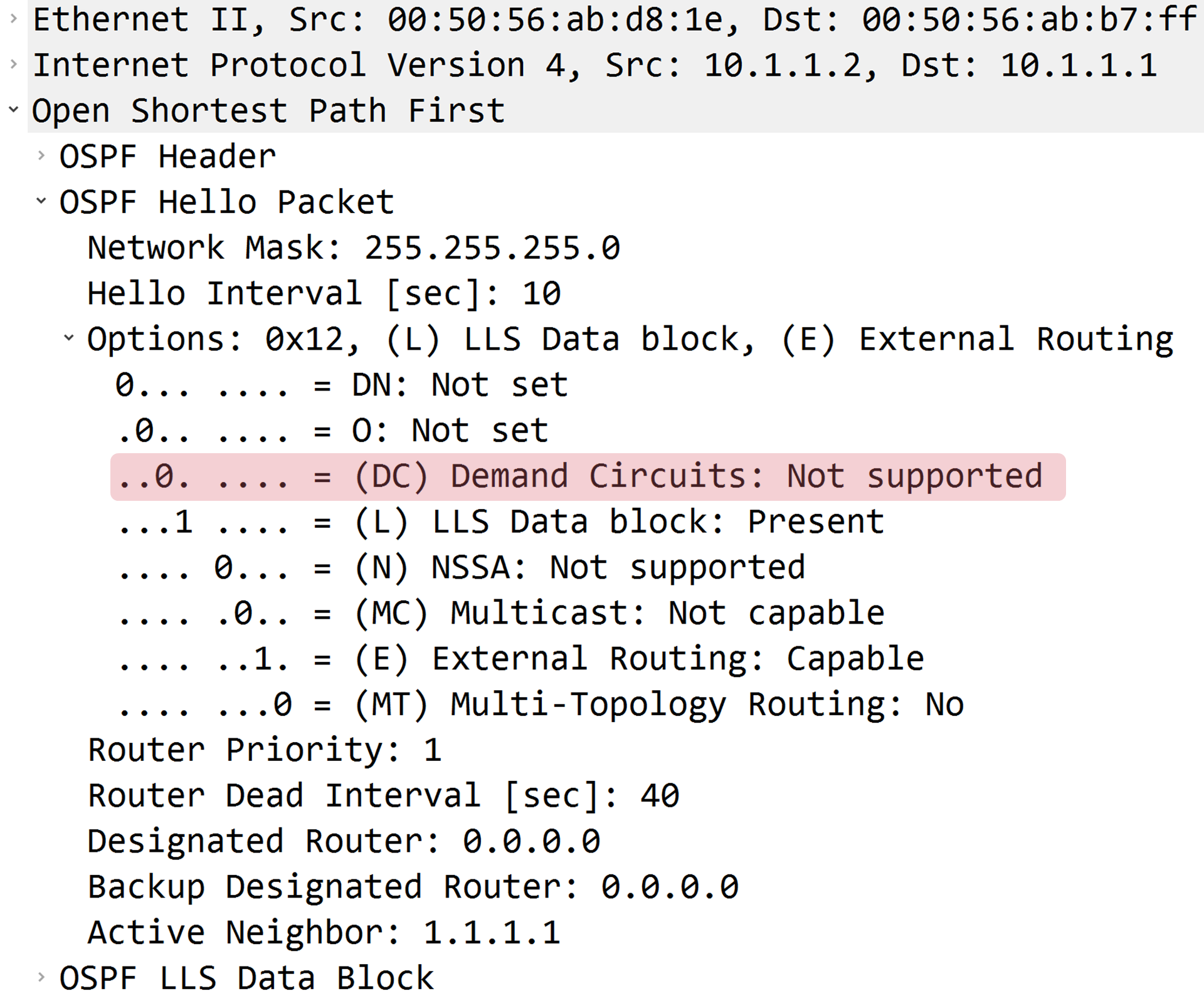
R2が送信したHelloパケットのDC bitに0がセットされていることが確認できます。
OSPFネイバーの状態確認
R1のR2でDemand Circuitが無効なことを認識しています。
R1#show ip ospf neighbor detail
 Neighbor 2.2.2.2, interface address 10.1.1.2, interface-id 6
    In the area 0 via interface GigabitEthernet2
    Neighbor priority is 0, State is FULL, 6 state changes
    DR is 0.0.0.0 BDR is 0.0.0.0
    Options is 0x32 in Hello (E-bit, L-bit)
    Options is 0x72 in DBD (E-bit, L-bit, O-bit)
    LLS Options is 0x1 (LR)
    Neighbor is up for 00:02:42
    Index 1/1/1, retransmission queue length 0, number of retransmission 0
    First 0x0(0)/0x0(0)/0x0(0) Next 0x0(0)/0x0(0)/0x0(0)
    Last retransmission scan length is 0, maximum is 0
    Last retransmission scan time is 0 msec, maximum is 0 msec
R2のR1でDemand Circuitが無効なことを認識しています。
R2#show ip ospf neighbor detail
 Neighbor 1.1.1.1, interface address 10.1.1.1, interface-id 6
    In the area 0 via interface GigabitEthernet2
    Neighbor priority is 0, State is FULL, 6 state changes
    DR is 0.0.0.0 BDR is 0.0.0.0
    Options is 0x32 in Hello (E-bit, L-bit)
    Options is 0x72 in DBD (E-bit, L-bit, O-bit)
    LLS Options is 0x1 (LR)
    Neighbor is up for 00:03:12
    Index 1/1/1, retransmission queue length 0, number of retransmission 0
    First 0x0(0)/0x0(0)/0x0(0) Next 0x0(0)/0x0(0)/0x0(0)
    Last retransmission scan length is 0, maximum is 0
    Last retransmission scan time is 0 msec, maximum is 0 msec
LSDBの状態確認
R1のLSDBに存在するR2が生成したLSA Type 1のDo Not Age Flagが0であることが確認できます。
R1#show ip ospf database

            OSPF Router with ID (1.1.1.1) (Process ID 1)

                Router Link States (Area 0)

Link ID         ADV Router      Age         Seq#       Checksum Link count
1.1.1.1         1.1.1.1         67          0x80000002 0x00DD1B 2
2.2.2.2         2.2.2.2         68          0x80000002 0x007D76 2
R2のLSDBに存在するR1が生成したLSA Type 1のDo Not Age Flagが0であることが確認できます。
R2#show ip ospf database

            OSPF Router with ID (2.2.2.2) (Process ID 1)

                Router Link States (Area 0)

Link ID         ADV Router      Age         Seq#       Checksum Link count
1.1.1.1         1.1.1.1         122         0x80000002 0x00DD1B 2
2.2.2.2         2.2.2.2         121         0x80000002 0x007D76 2
R1でDemand Circuitが有効
R1のg2でDemand Circuitを有効にします。

追加した設定
Demand Circuitはip ospf demand-circuitコマンドで有効化可能です。
interface GigabitEthernet2
 ip ospf demand-circuit
OSPFが動作しているインタフェースの状態確認
R1のg2でDemand Circuitが設定されており、かつ、Demand Circuitが有効なことが確認できます。
R1#show ip ospf interface
GigabitEthernet2 is up, line protocol is up
  Internet Address 10.1.1.1/24, Interface ID 6, Area 0
  Attached via Network Statement
  Process ID 1, Router ID 1.1.1.1, Network Type POINT_TO_POINT, Cost: 1
  Topology-MTID    Cost    Disabled    Shutdown      Topology Name
        0           1         no          no            Base
  Configured as demand circuit
  Run as demand circuit
  DoNotAge LSA allowed
  Transmit Delay is 1 sec, State POINT_TO_POINT
  Timer intervals configured, Hello 10, Dead 40, Wait 40, Retransmit 5
    oob-resync timeout 40
    Hello due in 00:00:04
  Supports Link-local Signaling (LLS)
  Cisco NSF helper support enabled
  IETF NSF helper support enabled
  Index 1/1/1, flood queue length 0
  Next 0x0(0)/0x0(0)/0x0(0)
  Last flood scan length is 1, maximum is 1
  Last flood scan time is 0 msec, maximum is 0 msec
  Neighbor Count is 1, Adjacent neighbor count is 1
    Adjacent with neighbor 2.2.2.2  (Hello suppressed)
  Suppress hello for 1 neighbor(s)
R2のg2でDemand Circuitが有効なことが確認できます。
R2#show ip ospf interface
GigabitEthernet2 is up, line protocol is up
  Internet Address 10.1.1.2/24, Interface ID 6, Area 0
  Attached via Network Statement
  Process ID 1, Router ID 2.2.2.2, Network Type POINT_TO_POINT, Cost: 1
  Topology-MTID    Cost    Disabled    Shutdown      Topology Name
        0           1         no          no            Base
  Run as demand circuit
  DoNotAge LSA allowed
  Transmit Delay is 1 sec, State POINT_TO_POINT
  Timer intervals configured, Hello 10, Dead 40, Wait 40, Retransmit 5
    oob-resync timeout 40
    Hello due in 00:00:00
  Supports Link-local Signaling (LLS)
  Cisco NSF helper support enabled
  IETF NSF helper support enabled
  Index 1/1/1, flood queue length 0
  Next 0x0(0)/0x0(0)/0x0(0)
  Last flood scan length is 1, maximum is 1
  Last flood scan time is 0 msec, maximum is 0 msec
  Neighbor Count is 1, Adjacent neighbor count is 1
    Adjacent with neighbor 1.1.1.1  (Hello suppressed)
  Suppress hello for 1 neighbor(s)
Helloパケットの確認
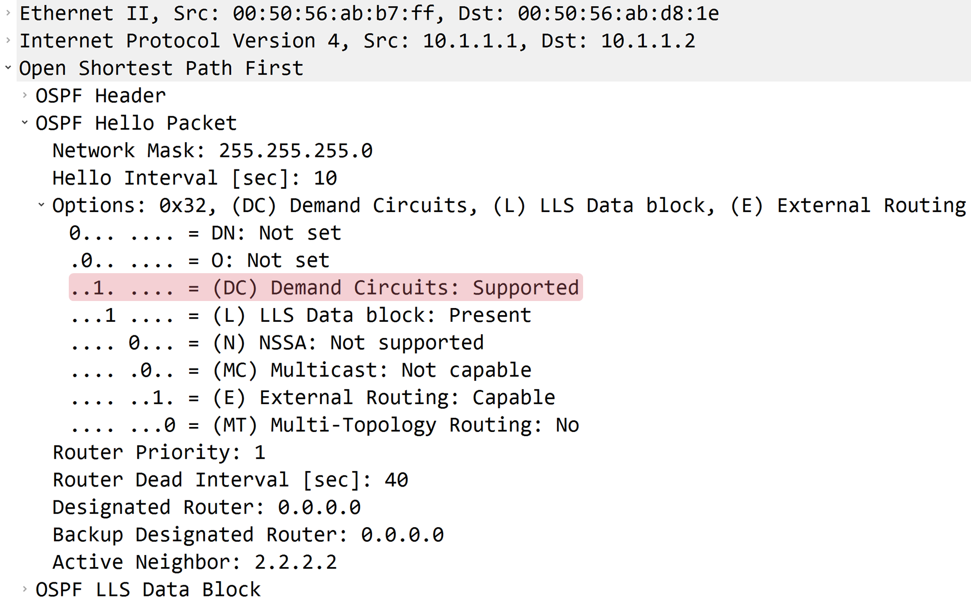
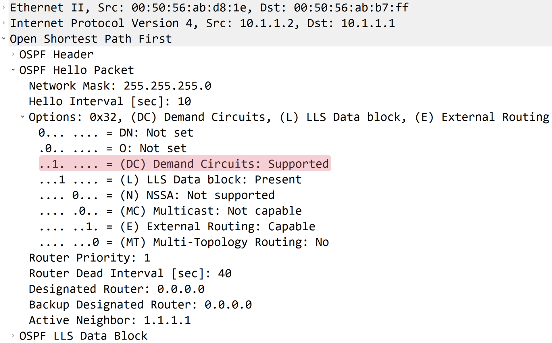
R1が送信したHelloパケットのDC bitに1がセットされていることが確認できます。
R2が送信したHelloパケットのDC bitに1がセットされていることが確認できます。
OSPFネイバーの状態確認
R1のR2でDemand Circuitが有効なことを認識しています。
R1#show ip ospf neighbor detail
 Neighbor 2.2.2.2, interface address 10.1.1.2, interface-id 6
    In the area 0 via interface GigabitEthernet2
    Neighbor priority is 0, State is FULL, 6 state changes
    DR is 0.0.0.0 BDR is 0.0.0.0
    Options is 0x32 in Hello (E-bit, L-bit, DC-bit)
    Options is 0x72 in DBD (E-bit, L-bit, DC-bit, O-bit)
    LLS Options is 0x1 (LR)
    Neighbor is up for 00:02:42
    Index 1/1/1, retransmission queue length 0, number of retransmission 0
    First 0x0(0)/0x0(0)/0x0(0) Next 0x0(0)/0x0(0)/0x0(0)
    Last retransmission scan length is 0, maximum is 0
    Last retransmission scan time is 0 msec, maximum is 0 msec
R2のR1でDemand Circuitが有効なことを認識しています。
R2#show ip ospf neighbor detail
 Neighbor 1.1.1.1, interface address 10.1.1.1, interface-id 6
    In the area 0 via interface GigabitEthernet2
    Neighbor priority is 0, State is FULL, 6 state changes
    DR is 0.0.0.0 BDR is 0.0.0.0
    Options is 0x32 in Hello (E-bit, L-bit, DC-bit)
    Options is 0x72 in DBD (E-bit, L-bit, DC-bit, O-bit)
    LLS Options is 0x1 (LR)
    Neighbor is up for 00:03:12
    Index 1/1/1, retransmission queue length 0, number of retransmission 0
    First 0x0(0)/0x0(0)/0x0(0) Next 0x0(0)/0x0(0)/0x0(0)
    Last retransmission scan length is 0, maximum is 0
    Last retransmission scan time is 0 msec, maximum is 0 msec
OSPFのLSDBの状態確認
R1のLSDBに存在するR2が生成したLSA Type 1のDo Not Age Flagが1であることが確認できます。
R1#show ip ospf database

            OSPF Router with ID (1.1.1.1) (Process ID 1)

                Router Link States (Area 0)

Link ID         ADV Router      Age         Seq#       Checksum Link count
1.1.1.1         1.1.1.1         69          0x80000002 0x00DD1B 2
2.2.2.2         2.2.2.2         1     (DNA) 0x80000002 0x007D76 2
R2のLSDBに存在するR1が生成したLSA Type 1のDo Not Age Flagが1であることが確認できます。
R2#show ip ospf database

            OSPF Router with ID (2.2.2.2) (Process ID 1)

                Router Link States (Area 0)

Link ID         ADV Router      Age         Seq#       Checksum Link count
1.1.1.1         1.1.1.1         1     (DNA) 0x80000002 0x00DD1B 2
2.2.2.2         2.2.2.2         106         0x80000002 0x007D76 2
R1でDemand Circuitが有効 & R2でDemand Circuitを拒否
R1のg2でDemand Circuitを有効にします。

追加した設定
ネイバーからのDemand Circuitの要求を無視するには、ip ospf demand-circuitコマンドのignoreオプションを指定します。
interface GigabitEthernet2
 ip ospf demand-circuit
interface GigabitEthernet2
 ip ospf demand-circuit ignore
OSPFが動作しているインタフェースの状態確認
R1のg2でDemand Circuitが設定されており、かつ、Demand Circuitが有効なことが確認できます。
R1#show ip ospf interface
GigabitEthernet2 is up, line protocol is up
  Internet Address 10.1.1.1/24, Interface ID 6, Area 0
  Attached via Network Statement
  Process ID 1, Router ID 1.1.1.1, Network Type POINT_TO_POINT, Cost: 1
  Topology-MTID    Cost    Disabled    Shutdown      Topology Name
        0           1         no          no            Base
  Configured as demand circuit
  Run as demand circuit
  DoNotAge LSA allowed
  Transmit Delay is 1 sec, State POINT_TO_POINT
  Timer intervals configured, Hello 10, Dead 40, Wait 40, Retransmit 5
    oob-resync timeout 40
    Hello due in 00:00:04
  Supports Link-local Signaling (LLS)
  Cisco NSF helper support enabled
  IETF NSF helper support enabled
  Index 1/1/1, flood queue length 0
  Next 0x0(0)/0x0(0)/0x0(0)
  Last flood scan length is 1, maximum is 1
  Last flood scan time is 0 msec, maximum is 0 msec
  Neighbor Count is 1, Adjacent neighbor count is 1
    Adjacent with neighbor 2.2.2.2  (Hello suppressed)
  Suppress hello for 1 neighbor(s)
R2のg2でDemand Circuitを拒否していることが確認できます。
R2#show ip ospf interface
GigabitEthernet2 is up, line protocol is up
  Internet Address 10.1.1.2/24, Interface ID 6, Area 0
  Attached via Network Statement
  Process ID 1, Router ID 2.2.2.2, Network Type POINT_TO_POINT, Cost: 1
  Topology-MTID    Cost    Disabled    Shutdown      Topology Name
        0           1         no          no            Base
  Ignore demand circuit auto-negotiation requests
  Transmit Delay is 1 sec, State POINT_TO_POINT
  Timer intervals configured, Hello 10, Dead 40, Wait 40, Retransmit 5
    oob-resync timeout 40
    Hello due in 00:00:03
  Supports Link-local Signaling (LLS)
  Cisco NSF helper support enabled
  IETF NSF helper support enabled
  Index 1/1/1, flood queue length 0
  Next 0x0(0)/0x0(0)/0x0(0)
  Last flood scan length is 1, maximum is 1
  Last flood scan time is 0 msec, maximum is 0 msec
  Neighbor Count is 1, Adjacent neighbor count is 1
    Adjacent with neighbor 1.1.1.1
  Suppress hello for 0 neighbor(s)
Helloパケットの確認
R1が送信したHelloパケットのDC bitに1がセットされていることが確認できます。

R2が送信したHelloパケットのDC bitに0がセットされていることが確認できます。

OSPFネイバーの状態確認
R1のR2でDemand Circuitが無効なことを認識しています。
R1#show ip ospf neighbor detail
 Neighbor 2.2.2.2, interface address 10.1.1.2, interface-id 6
    In the area 0 via interface GigabitEthernet2
    Neighbor priority is 0, State is FULL, 6 state changes
    DR is 0.0.0.0 BDR is 0.0.0.0
    Options is 0x32 in Hello (E-bit, L-bit)
    Options is 0x72 in DBD (E-bit, L-bit, O-bit)
    LLS Options is 0x1 (LR)
    Neighbor is up for 00:02:42
    Index 1/1/1, retransmission queue length 0, number of retransmission 0
    First 0x0(0)/0x0(0)/0x0(0) Next 0x0(0)/0x0(0)/0x0(0)
    Last retransmission scan length is 0, maximum is 0
    Last retransmission scan time is 0 msec, maximum is 0 msec
R2のR1でDemand Circuitが有効なことを認識しています。
R2#show ip ospf neighbor detail
 Neighbor 1.1.1.1, interface address 10.1.1.1, interface-id 6
    In the area 0 via interface GigabitEthernet2
    Neighbor priority is 0, State is FULL, 6 state changes
    DR is 0.0.0.0 BDR is 0.0.0.0
    Options is 0x32 in Hello (E-bit, L-bit, DC-bit)
    Options is 0x72 in DBD (E-bit, L-bit, DC-bit, O-bit)
    LLS Options is 0x1 (LR)
    Neighbor is up for 00:03:12
    Index 1/1/1, retransmission queue length 0, number of retransmission 0
    First 0x0(0)/0x0(0)/0x0(0) Next 0x0(0)/0x0(0)/0x0(0)
    Last retransmission scan length is 0, maximum is 0
    Last retransmission scan time is 0 msec, maximum is 0 msec
OSPFのLSDBの状態確認
R1のLSDBに存在するR2が生成したLSA Type 1のDo Not Age Flagが0であることが確認できます。
R1#show ip ospf database

            OSPF Router with ID (1.1.1.1) (Process ID 1)

                Router Link States (Area 0)

Link ID         ADV Router      Age         Seq#       Checksum Link count
1.1.1.1         1.1.1.1         59          0x80000002 0x00DD1B 2
2.2.2.2         2.2.2.2         60          0x80000002 0x007D76 2
R2のLSDBに存在するR1が生成したLSA Type 1のDo Not Age Flagが1であることが確認できます。
R2#show ip ospf database

            OSPF Router with ID (2.2.2.2) (Process ID 1)

                Router Link States (Area 0)

Link ID         ADV Router      Age         Seq#       Checksum Link count
1.1.1.1         1.1.1.1         5     (DNA) 0x80000002 0x00DD1B 2
2.2.2.2         2.2.2.2         94          0x80000002 0x007D76 2


コメント