今回はPCEでLink Colorを考慮してLSPを計算する際の動作を説明したいと思います。
概要
PCEによるLink Colorを考慮したLSPの計算
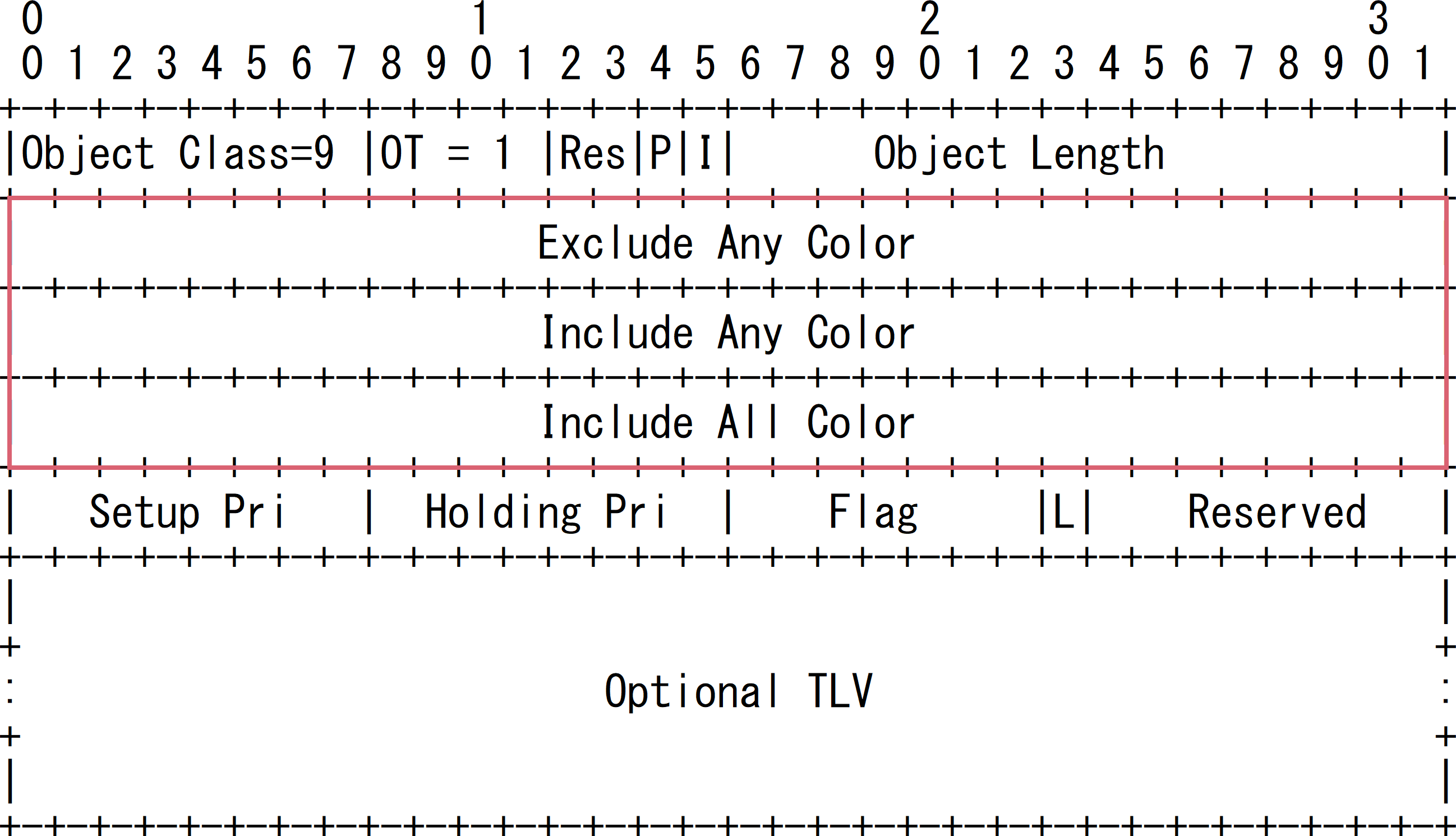
LSP計算時のLink Colorの制約はLSPA Objectに格納されて、PCCからPCEに送信されます。
これにより、PCEはLSPを計算時にColorの制約を考慮可能です
検証内容と設定
基本設定の内容
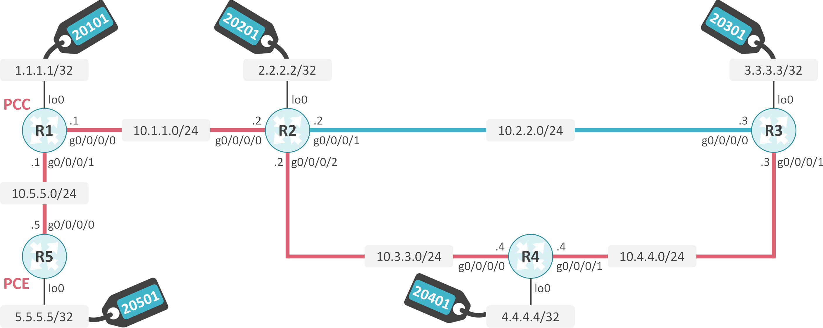
R1-R2-R3-R4-R5間でOSPF Area 0を構成します。
OSPFでSR-TEを有効にします。
R1-R2間、R1-R5間、R2-R4間、R3-R4間のリンクにColor REDを割り当てます。
R2-R3間のリンクにColor BLUEを割り当てます。
R1でLoopback Interfaceの1.1.1.1/32にPrefix SIDとして20101を割り当てます。
R3でLoopback Interfaceの2.2.2.2/32にPrefix SIDとして20201を割り当てます。
R3でLoopback Interfaceの3.3.3.3/32にPrefix SIDとして20301を割り当てます。
R4でLoopback Interfaceの4.4.4.4/32にPrefix SIDとして20401を割り当てます。
R5でLoopback Interfaceの5.5.5.5/32にPrefix SIDとして20501を割り当てます。
R5をPCE、R1をPCCとして動作させます。
R1からPCEに対して、3.3.3.3へのLSPの計算を依頼します。Color REDが割り当てられたリンクのみを使用してLSPを計算します。
初期設定
interface Loopback0
 ipv4 address 1.1.1.1 255.255.255.255
!
interface GigabitEthernet0/0/0/0
 ipv4 address 10.1.1.1 255.255.255.0
!
interface GigabitEthernet0/0/0/1
 ipv4 address 10.5.5.1 255.255.255.0
!
router ospf 1
 router-id 1.1.1.1
 segment-routing mpls
 area 0
  mpls traffic-eng
  interface Loopback0
   prefix-sid absolute 20101
  !
  interface GigabitEthernet0/0/0/0
   network point-to-point
  !
  interface GigabitEthernet0/0/0/1
   network point-to-point
  !
 !
!
segment-routing
 traffic-eng
  interface GigabitEthernet0/0/0/0
   affinity
    name RED
   !
  !
  interface GigabitEthernet0/0/0/1
   affinity
    name RED
   !
  !
  policy SR-TE_POLICY
   color 1 end-point ipv4 3.3.3.3
   autoroute
    include all
   !
   candidate-paths
    preference 10
     dynamic
      pcep
      !
     !
     constraints
      affinity
       include-any
        name RED
      !
      !
     !
    !
   !
  !
  affinity-map
   name RED bit-position 0
   name BLUE bit-position 1
  !
  pcc
   pce address ipv4 5.5.5.5
interface Loopback0
 ipv4 address 2.2.2.2 255.255.255.255
!
interface GigabitEthernet0/0/0/0
 ipv4 address 10.1.1.2 255.255.255.0
!
interface GigabitEthernet0/0/0/1
 ipv4 address 10.2.2.2 255.255.255.0
!
interface GigabitEthernet0/0/0/2
 ipv4 address 10.3.3.2 255.255.255.0
!
router ospf 1
 router-id 2.2.2.2
 segment-routing mpls
 area 0
  mpls traffic-eng
  interface Loopback0
   prefix-sid absolute 20201
  !
  interface GigabitEthernet0/0/0/0
   network point-to-point
  !
  interface GigabitEthernet0/0/0/1
   network point-to-point
  !
  interface GigabitEthernet0/0/0/2
   network point-to-point
!
segment-routing
 traffic-eng
  interface GigabitEthernet0/0/0/0
   affinity
    name RED
   !
  !
  interface GigabitEthernet0/0/0/1
   affinity
    name BLUE
   !
  !
  interface GigabitEthernet0/0/0/2
   affinity
    name RED
   !
  !
  affinity-map
   name RED bit-position 0
   name BLUE bit-position 1
interface Loopback0
 ipv4 address 3.3.3.3 255.255.255.255
!
interface GigabitEthernet0/0/0/0
 ipv4 address 10.2.2.3 255.255.255.0
!
interface GigabitEthernet0/0/0/1
 ipv4 address 10.4.4.3 255.255.255.0
!
router ospf 1
 router-id 3.3.3.3
 segment-routing mpls
 area 0
  mpls traffic-eng
  interface Loopback0
   prefix-sid absolute 20301
  !
  interface GigabitEthernet0/0/0/0
   network point-to-point
  !
  interface GigabitEthernet0/0/0/1
   network point-to-point
  !
 !
!
segment-routing
 traffic-eng
  interface GigabitEthernet0/0/0/0
   affinity
    name BLUE
   !
  !
  interface GigabitEthernet0/0/0/1
   affinity
    name RED
   !
  !
  affinity-map
   name RED bit-position 0
   name BLUE bit-position 1
interface Loopback0
 ipv4 address 4.4.4.4 255.255.255.255
!
interface GigabitEthernet0/0/0/0
 ipv4 address 10.3.3.4 255.255.255.0
!
interface GigabitEthernet0/0/0/1
 ipv4 address 10.4.4.4 255.255.255.0
!
router ospf 1
 router-id 4.4.4.4
 segment-routing mpls
 area 0
  mpls traffic-eng
  interface Loopback0
   prefix-sid absolute 20401
  !
  interface GigabitEthernet0/0/0/0
   network point-to-point
  !
  interface GigabitEthernet0/0/0/1
   network point-to-point
  !
 !
!
segment-routing
 traffic-eng
  interface GigabitEthernet0/0/0/0
   affinity
    name RED
   !
  !
  interface GigabitEthernet0/0/0/1
   affinity
    name RED
   !
  !
  affinity-map
   name RED bit-position 0
   name BLUE bit-position 1
pce
 address ipv4 5.5.5.5
!
interface Loopback0
 ipv4 address 5.5.5.5 255.255.255.255
!
interface GigabitEthernet0/0/0/0
 ipv4 address 10.5.5.5 255.255.255.0
!
router ospf 1
 distribute link-state
 router-id 5.5.5.5
 segment-routing mpls
 area 0
  mpls traffic-eng
  interface Loopback0
   prefix-sid absolute 20501
  !
  interface GigabitEthernet0/0/0/0
   network point-to-point
  !
 !
!
segment-routing
 traffic-eng
  interface GigabitEthernet0/0/0/0
   affinity
    name RED
   !
  !
  affinity-map
   name RED bit-position 0
   name BLUE bit-position 1
PCEとPCCの状態確認
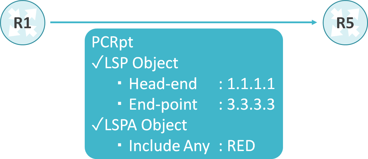
R1はR5に対して送信したPCRptメッセージのLSPA ObjectにColorの制約が格納されます。
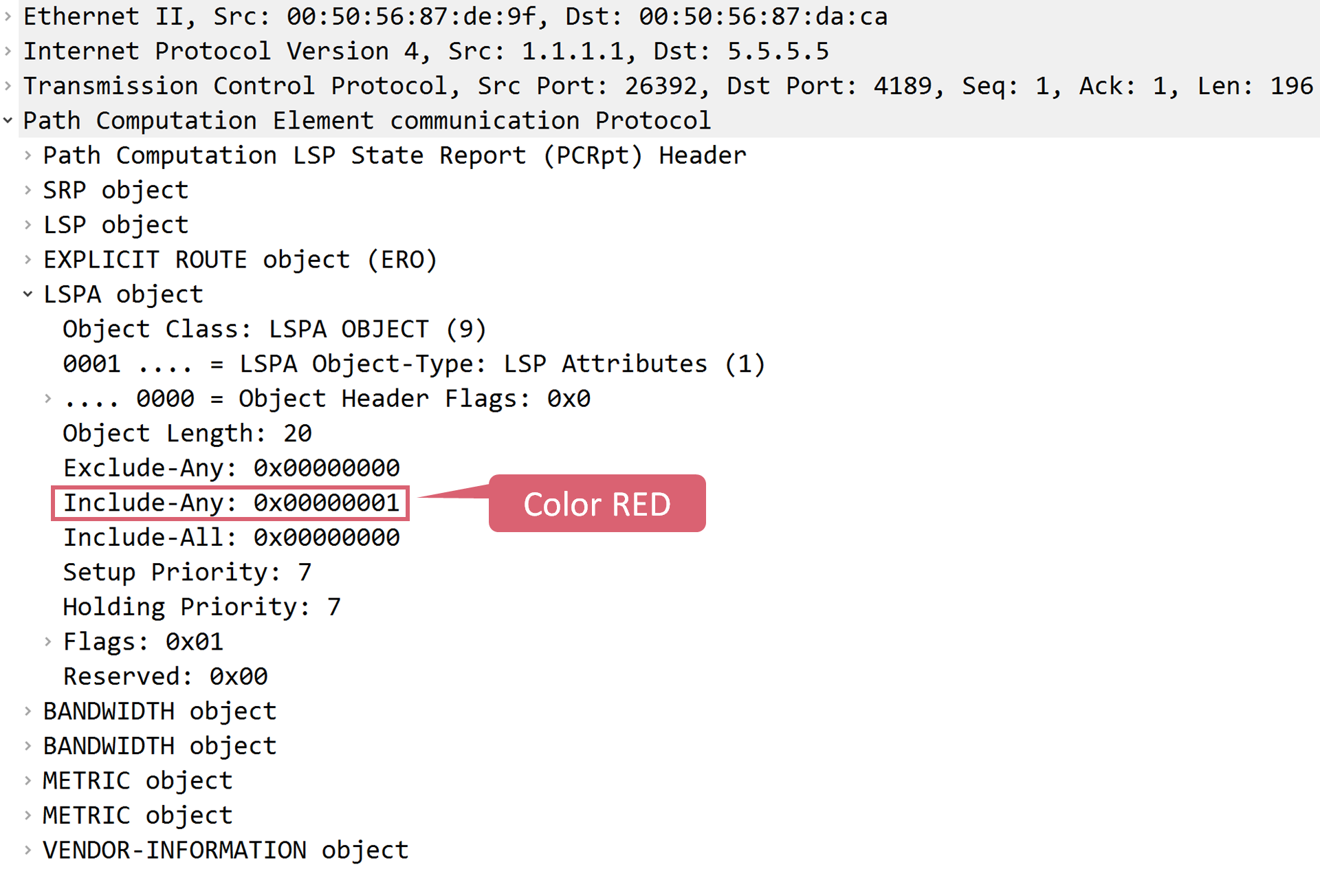
以下はR1がR5に送信したPCRptメッセージのキャプチャになります。LSPA ObjectのInclude-AnyにColor REDが格納されていることが確認できます。
R5が計算したLSPの情報を見ると、Colorを考慮してLSPを計算していることが確認できます。
RP/0/RP0/CPU0:R5#show pce lsp detail

PCE's tunnel database:
----------------------
PCC 1.1.1.1:

Tunnel Name: cfg_SR-TE_POLICY_discr_10
Color: 1
Interface Name: srte_c_1_ep_3.3.3.3
 LSPs:
  LSP[0]:
   source 1.1.1.1, destination 3.3.3.3, tunnel ID 13, LSP ID 1
   State: Admin up, Operation up
   Setup type: Segment Routing
   Binding SID: 24010
   Maximum SID Depth: 10
   Preference: 10
   Bandwidth: signaled 0 kbps, applied 0 kbps
   Affinity: exclude-any 0x0 include-any 0x1 include-all 0x0
   PCEP information:
     PLSP-ID 0xd, flags: D:1 S:0 R:0 A:1 O:1 C:0
   LSP Role: Single LSP
   State-sync PCE: None
   PCC: 1.1.1.1
   LSP is subdelegated to: None
   Reported path:
     Metric type: TE, Accumulated Metric 3
      SID[0]: Node, Label 20401, Address 4.4.4.4
      SID[1]: Node, Label 20301, Address 3.3.3.3
   Computed path: (Local PCE)
     Computed Time: Fri Jun 26 13:30:48 UTC 2020 (00:03:40 ago)
     Metric type: TE, Accumulated Metric 3
      SID[0]: Node, Label 20401, Address 4.4.4.4
      SID[1]: Node, Label 20301, Address 3.3.3.3
   Recorded path:
     None
   Disjoint Group Information:
     None
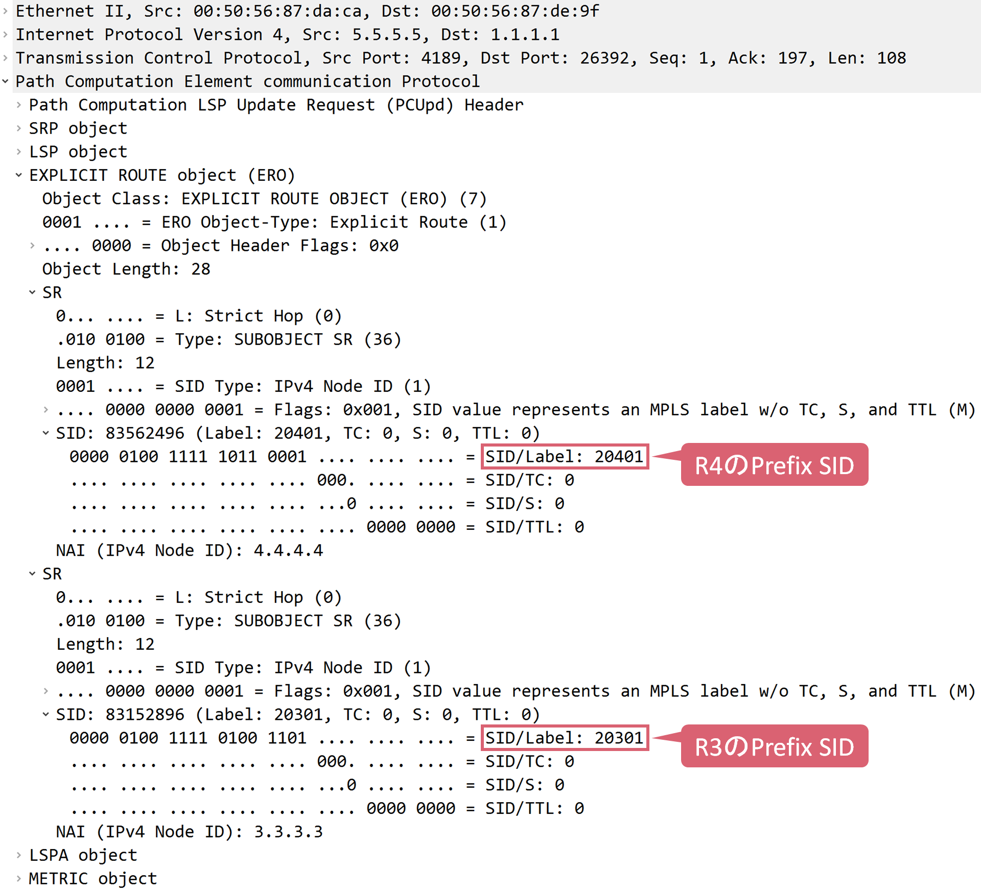
R5はLSP計算後、R1に対して、LSPの計算結果を格納したPCUpdメッセージを返信します。

以下はR5がR1に返信したPCUpdメッセージのキャプチャになります。R4とR3のPrefix SIDが格納されていることが確認できます。
R1はR5からLSPの計算結果を学習していることが確認できます。
RP/0/RP0/CPU0:R1#show segment-routing traffic-eng pcc lsp detail

PCC's SR policy database:
-------------------------
Symbolic Name: cfg_SR-TE_POLICY_discr_10
 LSP[0]:
  Source 1.1.1.1, Destination 3.3.3.3, Tunnel ID 7, LSP ID 1
  State: Admin up, Operation up
  Binding SID: 24007
  Setup type: SR
  Bandwidth: requested 0, used 0
  LSP object:
    PLSP-ID 0x7, flags: D:0 S:0 R:0 A:1 O:1 C:0
  Metric type: IGP, Accumulated Metric 2
  ERO:
    SID[0]: Node, Label 20401, NAI: 4.4.4.4
    SID[1]: Node, Label 20301, NAI: 3.3.3.3
SR-TE Policyの確認
R1はR5から学習したLSPの計算結果を基に、SR-TE Policyのインスタンスを生成していることが確認できます。
RP/0/RP0/CPU0:R1#show segment-routing traffic-eng policy

SR-TE policy database
---------------------

Color: 1, End-point: 3.3.3.3
  Name: srte_c_1_ep_3.3.3.3
  Status:
    Admin: up  Operational: up for 00:02:53 (since Jun 26 13:30:21.547)
  Candidate-paths:
    Preference: 10 (configuration) (active)
      Name: SR-TE_POLICY
      Requested BSID: dynamic
      PCC info:
        Symbolic name: cfg_SR-TE_POLICY_discr_10
        PLSP-ID: 13
      Constraints:
        Affinity:
          include-any:
          RED
        Maximum SID Depth: 10
      Dynamic (pce 5.5.5.5) (valid)
        Metric Type: TE,   Path Accumulated Metric: 3
          20401 [Prefix-SID, 4.4.4.4]
          20301 [Prefix-SID, 3.3.3.3]
  Attributes:
    Binding SID: 24010
    Forward Class: Not Configured
    Steering labeled-services disabled: no
    Steering BGP disabled: no
    IPv6 caps enable: yes
疎通確認
R1の1.1.1.1からR3の3.3.3.3へTracerouteを実施します。
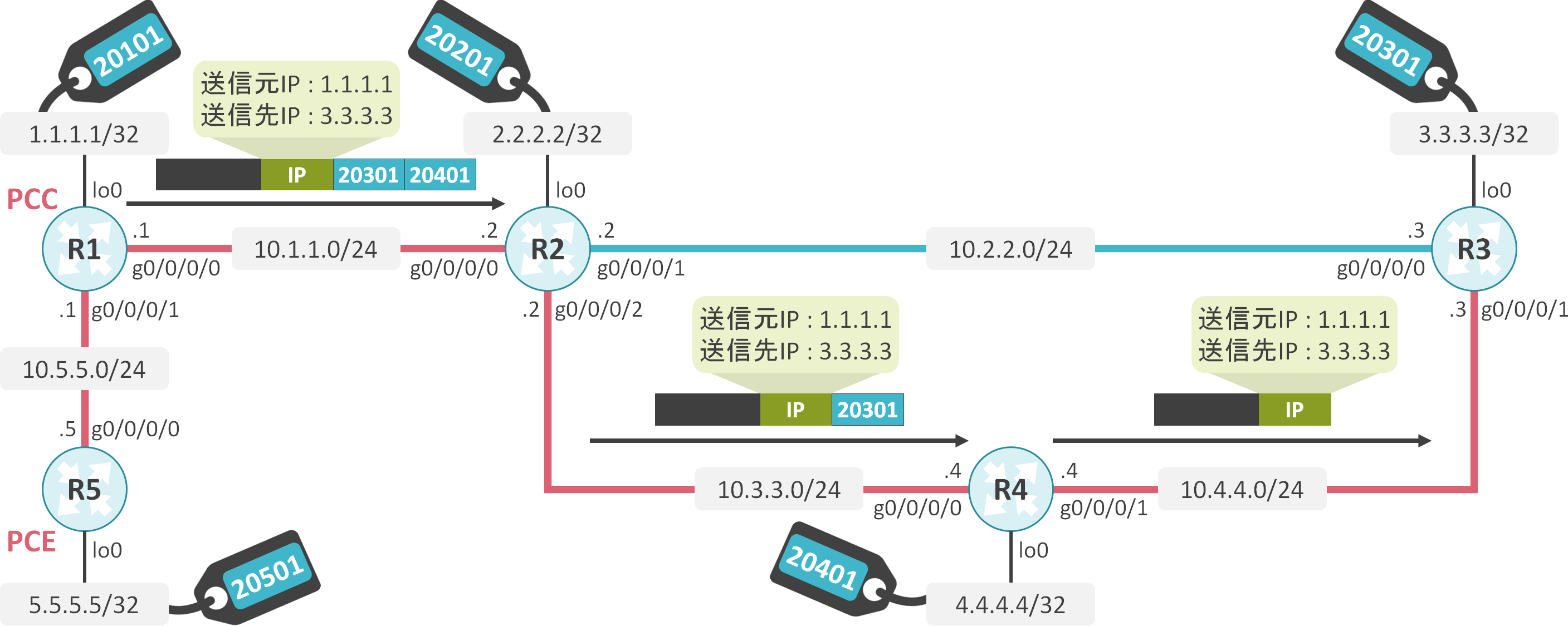
R1はSID 20401 20301をパケットに付加してR2に転送していることが確認できます。
RP/0/RP0/CPU0:R1#traceroute 3.3.3.3 source 1.1.1.1

Type escape sequence to abort.
Tracing the route to 3.3.3.3

 1  10.1.1.2 [MPLS: Labels 20401/20301 Exp 0] 28 msec  7 msec  13 msec
 2  10.3.3.4 [MPLS: Label 20301 Exp 0] 17 msec  18 msec  10 msec
 3  10.4.4.3 70 msec  *  28 msec


コメント